3 before you start, 1 worksurface layout, 2 screen assignment – DiGiCo SD11 User Manual
Page 7: 3 channel banks, 1 worksurface layout -2, 2 screen assignment -2, 3 channel banks -2, 4 using the control surface -3, Sd11 - getting started
SD11 - Getting Started
1-2
1.3 Before You Start
There are certain general operating principles and terms that should be understood before continuing to use this manual.
Please read this chapter carefully before proceeding.
1.3.1 Worksurface Layout ..............................................................
Mute and Channel Select Buttons
Option/All & 2nd Function Buttons
USB
Port
Headphone
Control
Talkback
Control
Solo Buss
Controls
Light
Controls
Assignable Rotaries
Screen Scroll Buttons
Channel Processing:
High and Low Pass Filters
4 Band Dynamic Parametric EQ
Dynamics Thresholds & On / Off
Channel Insert On/Off
Direct Out On/Off
Touchscreen
Quick
Select
Master Screen Assign
LCD Functions
Macro
Buttons
Snapshot Previous/Next
Bank Select Buttons
Master Level
Touch Turn Controls
Layer Select Button
Headphone
Socket
Undo/Redo &
Channel Select Buttons
1.3.2 Screen Assignment ...............................................................
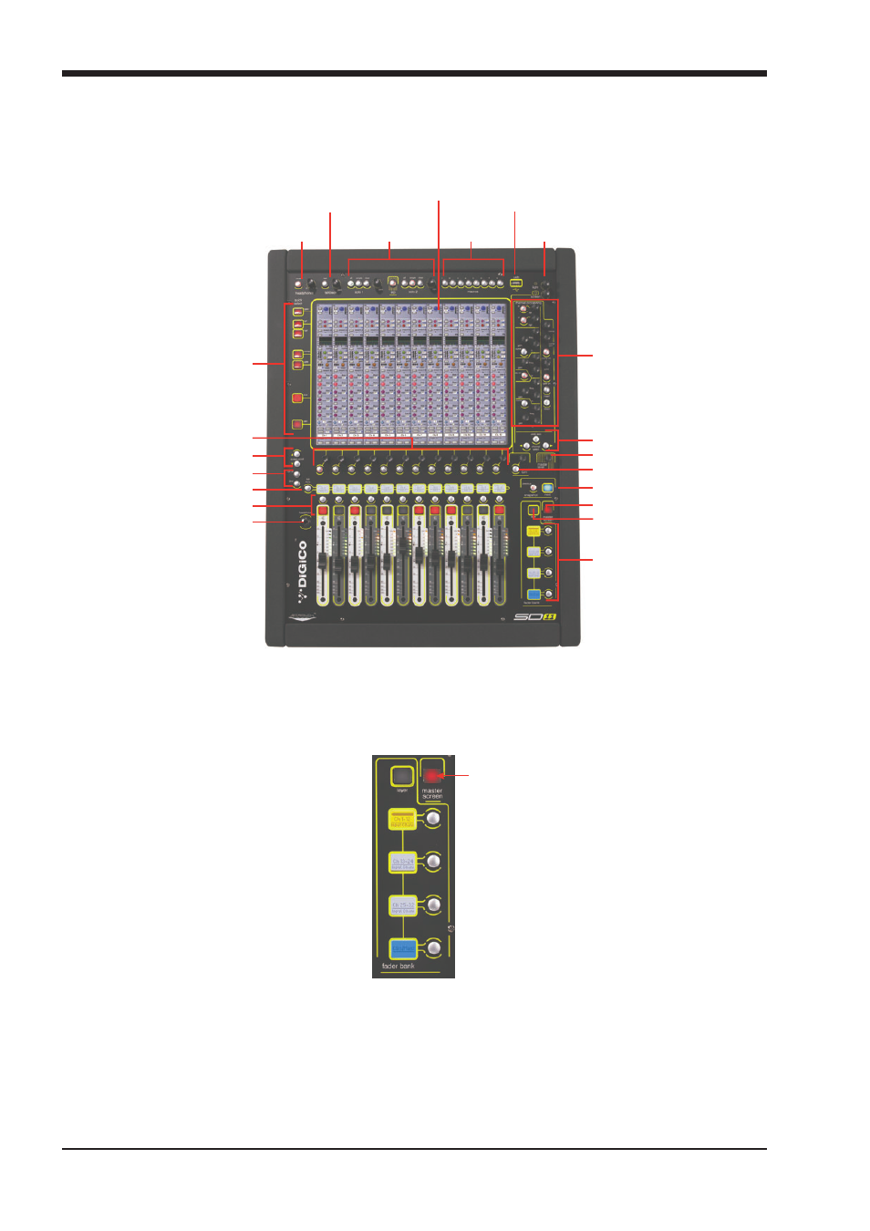
The SD11 has one central touchscreen which is used to access many of the consoles' functions. It displays either the in-channel
controls for the selected fader bank, or the Master menus. Press the master screen button to the right of the faders to switch
between these two displays.
Master Screen
Button
1.3.3 Channel Banks ......................................................................
The SD11's fader strips can be assigned to any of the console's fader banks. The SD11 has two layers, each with four banks of
12 faders. The active layer is selected using the layer button to the left of the master screen button, and the bank of channels
which is currently active on the control surface are defined using the fader bank buttons below them (see diagram above).
The position of the banks on the worksurface is defined in the Layout > Fader Banks panel. By default, the Input channels are
assigned to the first three banks of Layer 1, with Control Groups and Master fader are assigned to Layer 1 Bank 4, while the
different output channels are assigned to Layer 2. These bank assignments can be customised by the user and saved in a
session at any time.