Control terminal wiring, Connection diagram – Beijer Electronics BFI-H2 V1.12 User Manual
Page 23
User Guide Revision 1.12
23
4.7. Control Terminal Wiring
All analog signal cables should be suitably shielded. Twisted pair cables are recommended.
Power and Control Signal cables should be routed separately where possible, and must not be routed parallel to each other
Signal levels of different voltages e.g. 24 Volt DC and 110 Volt AC, should not be routed in the same cable.
Maximum control terminal tightening torque is 0.5Nm
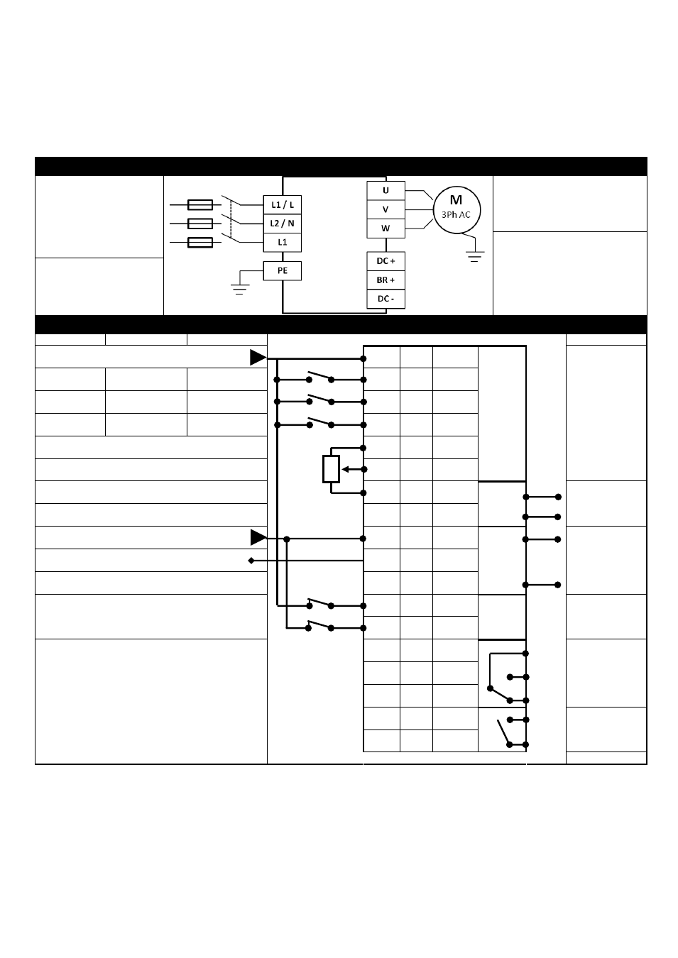
4.8. Connection Diagram
4.8.1. Power Terminal Designations
Incoming Mains Power Supply
For 1 Phase Supply, connect to
L1/L and L2/N terminals.
For 3 Phase Supply, connect to
L1, L2 & L3 terminals.
Phase sequence is not
important.
Motor Connections
Connect the motor to the U, V & W
terminals.
The motor earth must be connected
to the drive
Optional Brake Resistor & DC Bus
Connections
Where a Brake resistor is used, it
must be connected to the BR+ and
DC- terminals
Protective Earth / Ground
connection.
The drive must be Earthed /
Grounded
4.8.2. Control Terminal Connections & Factory Settings
Open
Closed
+24V Supply (100mA) / External Input
+24V
1
Digital Input 1
Run (Enable)
Stop
DIN1
2
Digital Input 2
Forward Rotation
Reverse Rotation
DIN2
3
Digital Input 3
Analog Speed Ref
Preset Speed
DIN3
4
Digital Inputs : 8 – 30 Volt DC
+ 10 Volt, 10mA Output
+10V
5
Analog Input 1
AIN1
6
0V
7
0V
Output Speed
Analog Output : 0 – 10 Volt / 4-20mA, 20mA Max
8
AOUT1
0 Volt Supply / External Input
0V
9
0V
Output Current
Analog Input 2
AIN2
10
Analog Output : 0 – 10 Volt / 4-20mA, 20mA Max
11
AOUT2
External Hardware Enable Circuit
STO+
12
STO-
13
Relay Contacts
250VAC / 30VDC
5A Maximum
14
RL1-C
Healthy
/ Fault
15
RL1-NO
16
RL1-NC
17
RL2-A
Running
18
RL2-B