Beijer Electronics AN-BEI-E2-038 User Manual
Page 6
APPLICATION NOTE AN‐BEI‐E2‐038
Date: 15/02/12
AN‐BEI‐E2‐038 Modbus RTU Control and Register Mapping
6
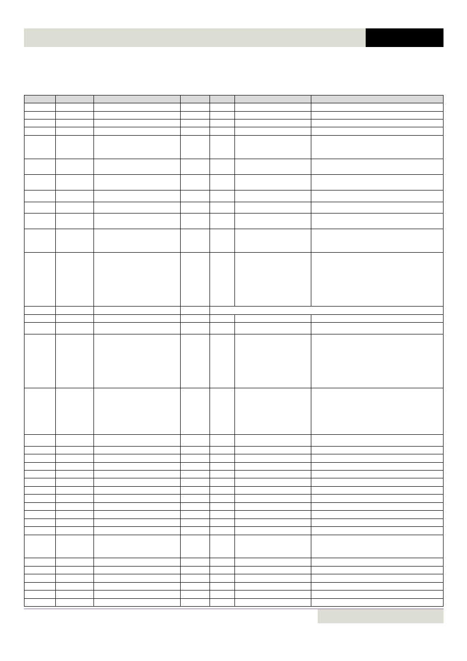
Table 2: Parameter registers
All user adjustable parameters within the drive are accessible by Modbus, and can be Read or Written to. For further
information regarding the parameter functions and specific settings, please refer to the User Guide.
Register
Parameter
Description
Format
Min
Max
Data format
129
01
Max speed limit
U16
0
5*P‐09
Internal value (3000 = 50.0Hz)
130
02
Min speed limit
U16
0
P‐01
Internal value (3000 = 50.0Hz)
131
03
Accel ramp time
U16
0
60000
2dp, e.g. 300=3.00s
132
04
Decel ramp time
U16
0
60000
2dp, e.g. 300=3.00s
133
05
Stop mode select
U16
0
2
0: Ramp to stop
1: Coast to stop
2: Ramp to stop
134
06
Energy save
U16
0
1
0: Disabled
1: Enabled
135
07
Motor rated voltage
U16
0
250
500
136
08
Motor rated current
U16
0
Drive Rating Dependent
1dp, e.g. 100 = 10.0A
137
09
Motor rated frequency
U16
25
500
Data unit is in Hz
138
10
Motor rated speed
U16
0
30000
Maximum value equals to the sync speed of a
typical 2‐pole motor
139
11
Boost voltage value
U16
0
Size 1 ‐ 0 to 200
Size 2 ‐ 0 to 150
Size 3 ‐ 0 to 100
1dp, e.g. 100 = 10.0%
140
12
Control mode
U16
0
6
0: Terminal Control
1: Keypad forward only
2: Keypad forward and reverse
3: Modbus control mode
4: Modbus control with ramp control
5 : PID control
6 : PID control with analog speed sum
141
13
Trip log
U16
See Appendix for Details
142
14
Access code
U16
0
9999
143
15
Digital input function
U16
0
12
See user guide for function details
144
16
Analog input format
U16
0
6
0: 0…10V
1: b 0…10V
2: 0…20mA
3: t 4…20mA
4: r 4…20mA
5: t 20…4mA
6: r 20…4mA
145
17
Effective switching frequency
U16
0
5
(Drive Rating Dependent)
0 = 4KHz
1 = 8KHz
2 = 12Khz
3 =16KHz
4 = 24KHz
5 = 32KHz
146
18
Relay output function
U16
0
7
See user guide for function details
147
19
Digital output limit
U16
0
1000
100 = 10.0%
148
20
Preset speed 1
U16
‐P‐01
P‐01
Internal value (3000 = 50.0Hz)
149
21
Preset speed 2
U16
‐P‐01
P‐01
Internal value (3000 = 50.0Hz)
150
22
Preset speed 3
U16
‐P‐01
P‐01
Internal value (3000 = 50.0Hz)
151
23
Preset speed 4
U16
‐P‐01
P‐01
Internal value (3000 = 50.0Hz)
152
24
2
nd
deceleration ramp
U16
0
2500
250 = 2.50s
153
25
Analog output function
U16
0
9
See user guide for function details
154
26
Skip frequency
U16
0
P‐01
Internal value (3000 = 50.0Hz)
155
27
Skip freq band
U16
0
P‐01
Internal value (3000 = 50.0Hz)
156
28
V/F adjust voltage
U16
0
P‐07
100 = 100V
157
29
V/F adjust frequency
U16
0
P‐09
50 = 50Hz
158
30
Start mode select
U16
0
6
0: Edgr‐r
1: Auto_0
2…6: Auto_1 to Auto_5
159
31
Keypad restart mode
U16
0
3
See user guide for details
160
32
DC injection enable
U16
0
250
250= 25.0s
161
33
Spin start enable
U16
0
1
162
34
Brake circuit enable
U16
0
2
See user guide for function details
163
35
Analog input scaling
U16
0
5000
100 = 10%
164
36
Drive address (Low byte)
0
63
Drive comms address