Modbus ramp control time – Beijer Electronics AN-BEI-E2-038 User Manual
Page 3
APPLICATION NOTE AN‐BEI‐E2‐038
Date: 15/02/12
AN‐BEI‐E2‐038 Modbus RTU Control and Register Mapping
3
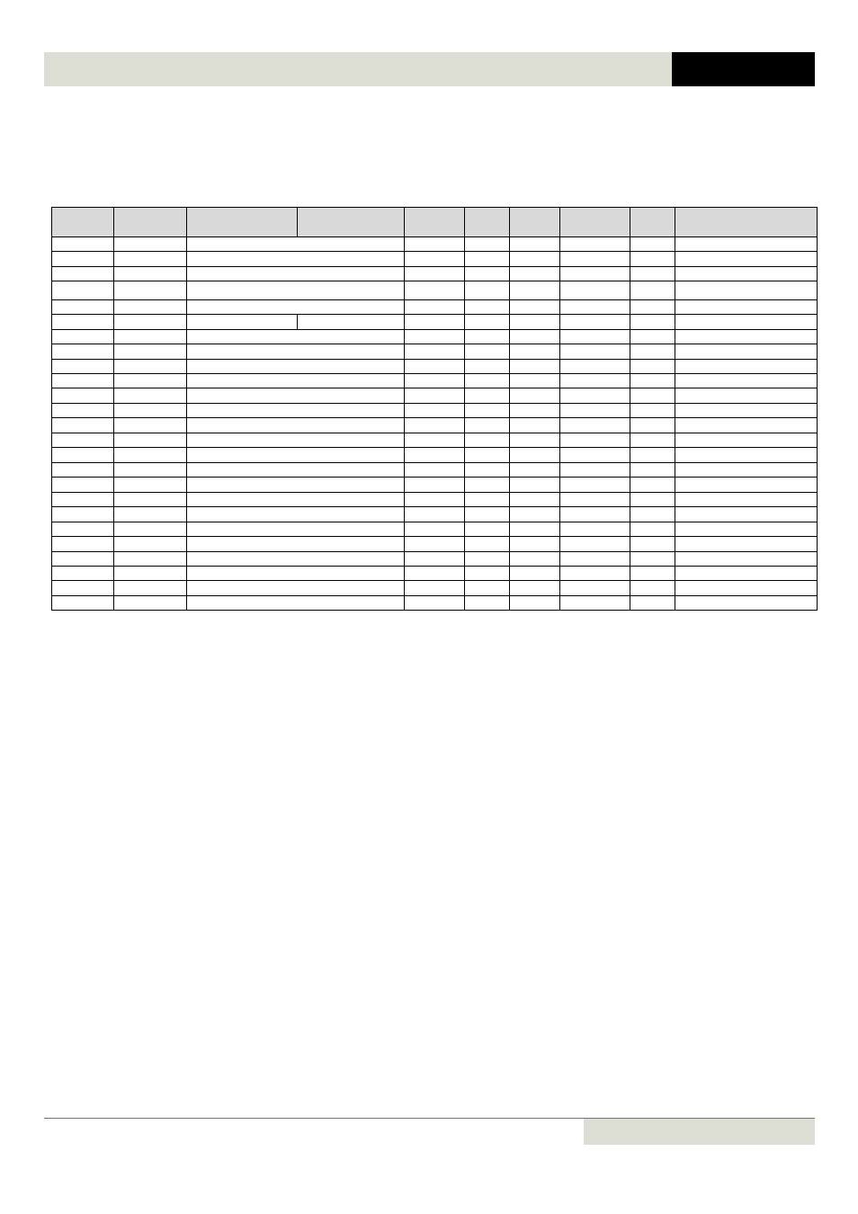
Memory Map:
Table 1: Control and status registers
Note : All registers are Holding Registers
Register
Number
Parameter
Number
Upper byte
Lower Byte
Format
Min
Max
Command
Type
Scaling
1*
‐
Control Word
WORD
0
15
03,06
R/W
See Below
2*
‐
Frequency Setpoint
S16
0
5000
03,06
R/W
1dp, e.g. 100 = 10.0Hz
3*
‐
Reserved
‐
‐
‐
03,06
R/W
4*
‐
Modbus ramp control time
U16
0
60000
03,06
R/W
2dp, e.g. 500 = 5.00s
5
‐
Reserved
‐
‐
‐
03
R
6*
‐
Error code
Drive status
‐
‐
‐
03
R
See Below
7*
‐
Output Frequency
S16
0
5000
03
R
1dp, e.g. 100 = 10.0Hz
8*
‐
Motor Current
U16
0
‐
03
R
1dp, e.g. 100 = 10.0A
9*
‐
Reserved
‐
‐
‐
03
R
10
‐
Reserved
‐
‐
‐
03
R
11
P00‐04
Digital Input Status
WORD
0000
1111
03
R
See Below
12
P00‐20
Rating ID
U16
‐
‐
03
R
Internal Value
13
P00‐20
Power rating
U16
‐
‐
03
R
2dp, e.g. 37 = 0.37kW / HP
14
P00‐20
Voltage rating
U16
‐
‐
03
R
Supply Voltage
15
P00‐18
IO processor software version
U16
‐
‐
03
R
2dp, e.g. 103 = 1.03
16
P00‐18
Motor control processor software version
U16
‐
‐
03
R
2dp, e.g. 103 = 1.03
17
P00‐20
Drive type
U16
‐
‐
03
R
Internal Code
18
‐
Reserved
‐
‐
‐
03
R
19
‐
Reserved
‐
‐
‐
03
R
20
P00‐01
Analog 1 input result
U16
0
1000
03
R
1dp, e.g. 500 = 50.0%
21
P00‐02
Analog 2 input result
U16
0
1000
03
R
1dp, e.g. 500 = 50.0%
22
P00‐03
Speed reference value
S16
0
5000
03
R
1dp, e.g. 500 = 50.0Hz
23
P00‐08
DC bus voltages
U16
0
1000
03
R
600 = 600 Volts
24
P00‐09
Drive temperature
S16
‐10
150
03
R
50 = 50°C
25 to 30
‐
Reserved
‐
‐
‐
03
R
* When using the external fieldbus gateways (PROFIBUS, DEVICENET, ETHERNET) these registers are available.
Format
WORD = WORD Format, functions assigned to individual bits
S16 = Signed 16 Bit Integer
U16 = Unsigned 16 bit Integer