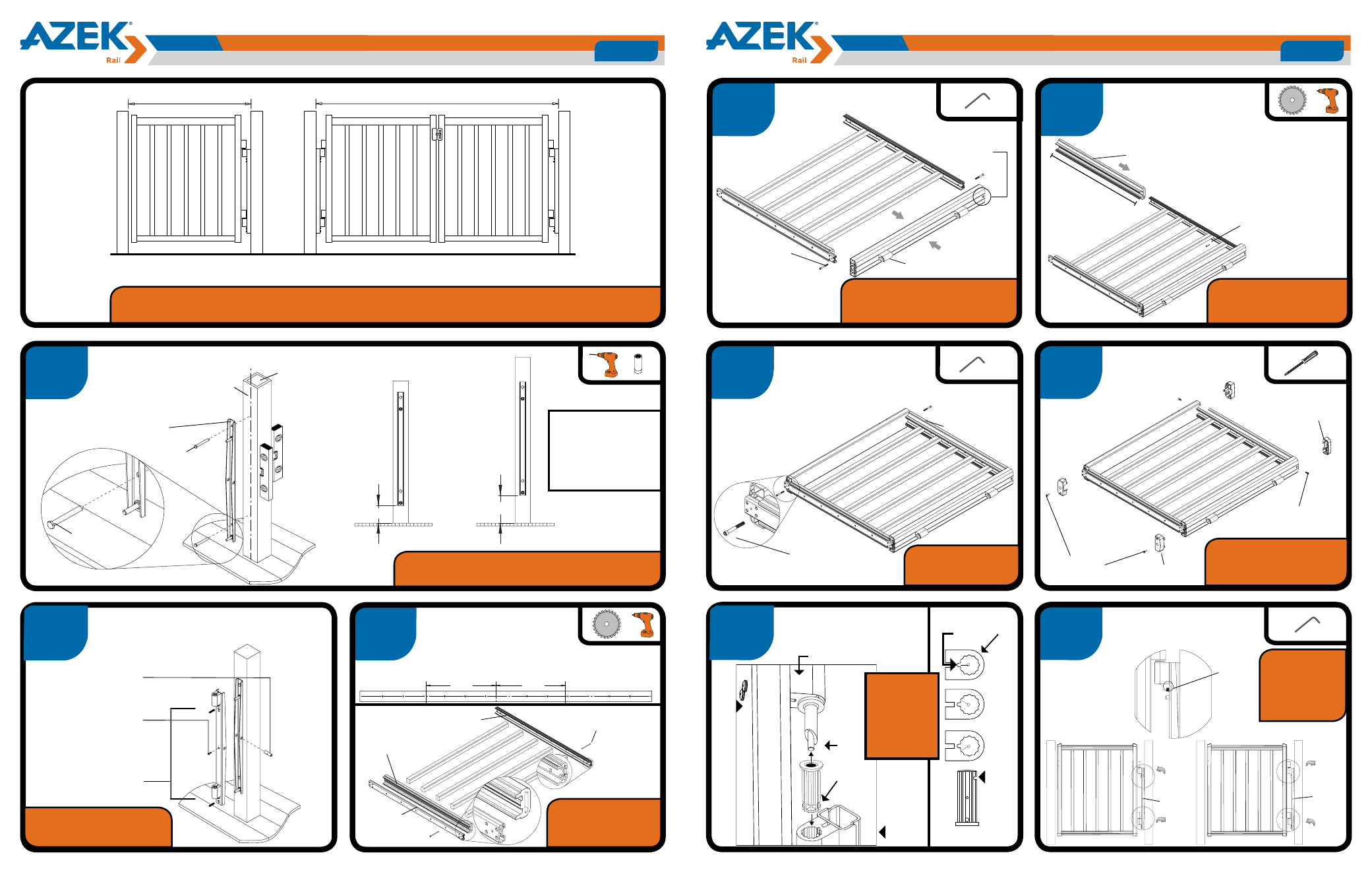
Page 2, Page 3, Slide on then fasten top rail – AZEK Gate User Manual
Page 2: Attach inner hinge plate to post, Assemble end caps, Adjust level of gate using setscrews, shown, Assemble hinge side end, Tools
4”
gap
42”gate
4”
gap
6 3/8”
3 3/8”
• Do not over
torque screws
into post.
1
6
2
8
3
4
5
Assemble Outer Hinge Plate
Drop Gate Assembly
onto Hinge Assembly
Assemble Latch Side
End and fully tighten
shoulder screws
Assemble Balusters
to Top Extrusion and
Bottom Rail/Bottom Extrusion
Slide on then
Fasten Top Rail
Assemble Hinge Side End
step 1
step 2
6 3/
8
2. Lock Hinge Pin
in Place with 3/4”
#10 Flat Head Screw
1. Insert Hinge Pin
step 4
step 5
step 6
step 7
1/4-20 Shoulder
Screws (x8)
Hinge Side
step 4
step 5
step 6
step 7
2. Slide on Hand Rail
3. Fasten with #8
Wood Screws (x4)
Tools
Level
Phillips Screw Driver
Wrench
Allen Keys
Drill
Attach Inner Hinge Plate to Post.
Tools
Level
Phillips Screw Driver
Wrench
Allen Keys
Drill
Hinges Pre-Assembled
3/8 Lag Screw
(x2)
Drill 5/16” Pilot Holes for
Lag Screws centered on post.
Sleeve
Post
Lag screw
goes above
threaded stud
3. Insert 3/8-16
set screw
1.
2.
Balusters need to
be trimmed 1/4” for
Trademark Rails.
Check hinge extrusions for alignment
with straightedge across both extrusions.
Loosen screws and adjust if necessary.
Check local code
requirements as to
required distance
between balusters to
avoid child entrapment.
Top Extrusion
Bottom
Extrusion
Cut Bottom
Rail to 34 1/2”
3” #8 Wood
Screws (x12)
Do not fully tighten shoul-
der screws until second side
end is attached in Step 6.
Be sure to cut top
rail accurately to
avoid excessive gap.
1. Cut Hand Rail
to 34 1/2”
7
Assemble End Caps*
Latch Side
1/4-20 Pan
Head Screws (x2)
Bottom
End Cap (x2)
1/4-20 Flat Head
Screws (x2)
Top End
Cap (x2)
Tools
Level
Phillips Screw Driver
Wrench
Allen Keys
Drill
Phillips
3.
3.
17 1/4
17 1/4
Tools
Level
Phillips Screw Driver
Wrench
Allen Keys
Drill
9
Adjust Level of Gate
Using Setscrews, shown.
step 10
step 9
Setscrew
step 10
step 9
TO ANGLE GATE UP:
Loosen
set screw
Tighten
set screw
Pivot
step 10
step 9
TO ANGLE GATE DOWN:
Loosen
set screw
Tighten
set screw
Pivot
Tools
Level
Phillips Screw Driver
Wrench
Allen Keys
Drill
Latch Side
1/4-20 Shoulder
Screws (x4)
1/4-20 Shoulder
Screws (x4)
To ensure baluster spacing, find center between holes & measure 17 1/4” to cut.
CUT
CUT
Tools
Level
Phillips Screw Driver
Wrench
Allen Keys
Drill
Be sure BOTH inner hinge plate and post are
properly secured, square, and plumb.
Hinge Plate Orientation
Screw hole goes
toward the top.
Closed
30°
Open
Positive
Close
Gate
Post
Tools
Level
Phillips Screw Driver
Wrench
Allen Keys
Drill
For a 2” gap:
(36” gate: 1 3/8” gap)
(42” gate: 4 3/8” gap)
Ref.
Mark
Cam
Cam
Ref.
Mark
36”gate
Ref.
Mark
Tighten all
Shoulder Screws
*Please refer to step
7a for additional dou-
ble gate instructions.
NOTE: Gate Kit will not work with Tall Boys (steel surface mount bracket)
Read all instruction prior to assembling gate components for either single or double gate
Reference
mark on cam
needs to line
up opposite
reference
mark on hinge
extrusion.
A 42-1/4” opening between post sleeves is
required for installation of a single gate.
A 83-1/4” opening between post sleeves is required for
installation of a double gate.
42-1/4”
83-1/4”
GATE INSTALLATION GUIDELINES for
AZEK Premier AZEK Trademark
Page 2
GATE INSTALLATION GUIDELINES for
AZEK Premier AZEK Trademark
Page 3
© 2012 All rights reserved. AZEK Building Products, Inc.
www.AZEK.com
© 2012 All rights reserved. AZEK Building Products, Inc.
www.AZEK.com
Hinge Extrusion
Hinge
Ext.
Measure to Bottom of Plate
This Cut
is Critical!
Check level
of Gate while
Gate is in
the Closed
Position.
Note: Check hinge extrusions for
alignment with straightedge across
both extrusions. Loosen
screws and
adjust if necessary.