Vaddio WallVIEW H700 Quick-Connect CCU User Manual
Page 2
Quick-Connect CCU H700
Quick-Connect CCU H700 Installation and User Guide 341-739 Rev. B Page 2 of 12
UNPACKING
Carefully remove and identify the following parts for the Quick-Connect CCU H700 system:
• One (1) - Vaddio EZCamera Interface Module CCU (EZIM CCU)
• One (1) - Vaddio EZIM CCU to HD Break Out Cable
• One (1) - Vaddio Quick-Connect CCU Universal (1-RU Rack Mountable)
• One (1) - Vaddio Thin Profile Wall Mount
• One (1) - 36V PowerRite Power Supply with AC Cord Set
• One (1) - EZCamera Control Adapter (RJ-45 to DB-9)
• One (1) - 2-position Phoenix Connector for Tally
• Mounting
Hardware
• Documentation
Vaddio
Manual
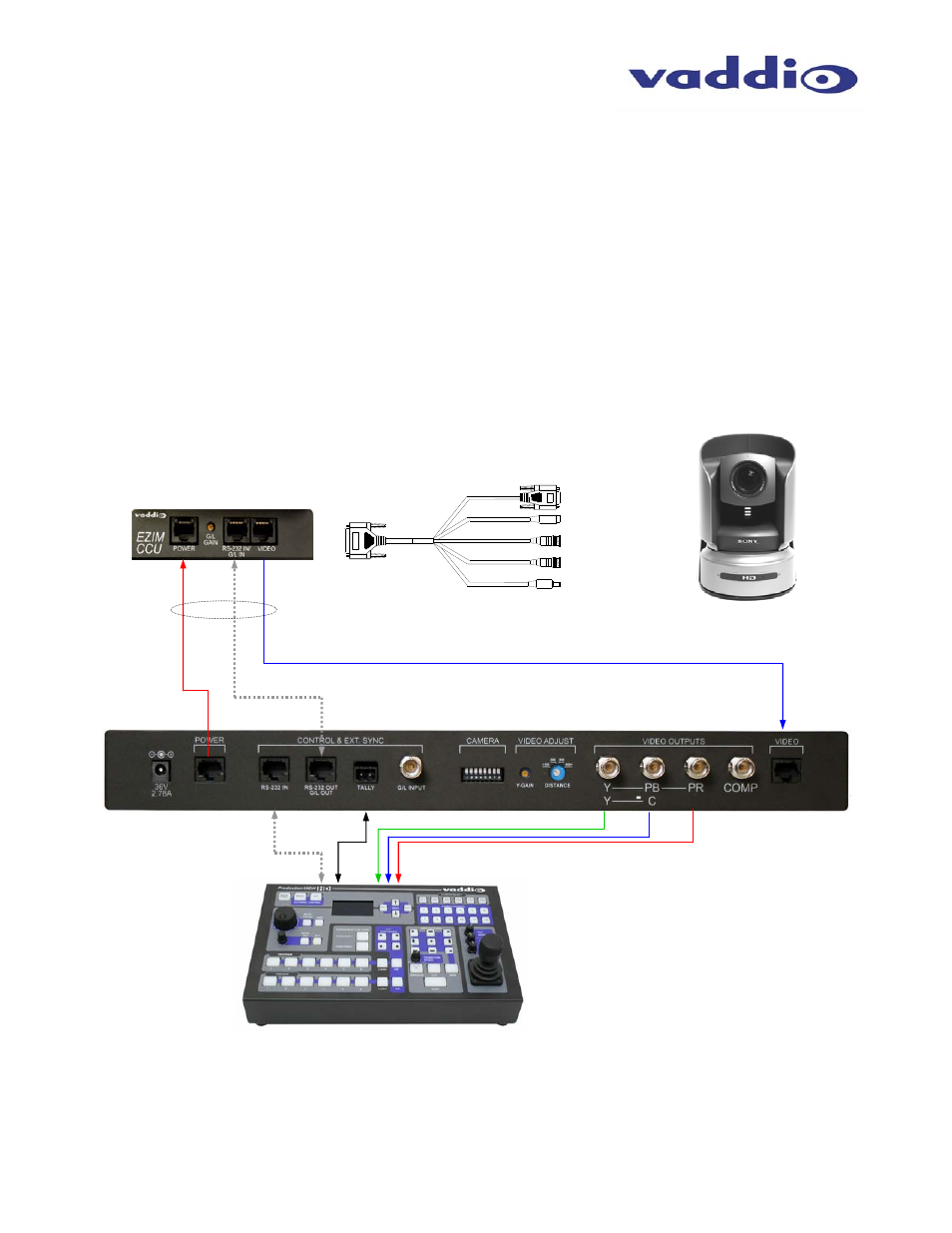
Wiring Diagram Example:
CAT-5 Cables
up to 500’
HD Break-out
Cable
EZIM CCU
Power
RS-232
HD Video on CAT-5
RS-232 Tally
ProductionVIEW HD
HD VIDEO OUT (Y, Pb, Pr)
RS-232 IN
SD VIDEO OUT (SD card required)
G/L (Not Used)
POWER
Quick-Connect CCU
BRC-H700 Camera, Wall Mount
with EZIM CCU (behind camera)
Component HD
Figure 2:
The Quick-Connect CCU System uses a Cat. 5 (all 4-pairs) for power to ensure the motors receive the required
current to operate properly. The Video Cat. 5 cable uses all four pairs for video. The RS-232 Cat. 5 provides communication
to the camera for CCU and PTZ control and G/L (where applicable) to the camera. These Cat. 5 cables can be run up to
500’ (152.4m). See Appendix 1 for wiring and pin-out information. NOTE: A direct RS-232 Cat. 5 cable is required for each
Quick-Connect CCU and camera. Daisy-Chain configurations are not supported with Quick-Connect CCU.
+
G