Installation instructions – Vaddio OneLINK User Manual
Page 6
OneLINK
OneLINK for Cisco Precision HD Cameras - Installation and User Guide 342-0122 Rev. G Page 6 of 12
INSTALLATION INSTRUCTIONS
Installation is simplified in that no custom cables or expensive multi-coax plenum cables are needed and no
local power outlets are required near the camera bracket. All RJ-45 connectors are to be terminated using
TIA/EIA 568B standard.
Before installing the OneLINK System:
Choose a camera mounting location while paying close attention to camera viewing angles, lighting
conditions, possible line of site obstructions, and checking for in-wall obstructions.
Pre-wire all cabling as required from the camera location to the Quick-Connect OneLINK.
Always test all terminations with a Cat-5e tester to ensure proper pin-out of cabling. Do not use “pass-
thru” type RJ-45 connectors (see note at the bottom of page 3).
The camera mount can be mounted directly to a 2-gang wall box or to drywall using the supplied anchors.
If daisy-chaining multiple PrecisionHD cameras, make sure that cabling is run from camera to camera to
support Cisco’s daisy-chain wiring design (see the Cisco manual).
Note: There are some caveats about the Cisco daisy-chain that are important to know when using
OneLINK. If the system loses power it will not see the 2
nd
camera in the daisy chain unless the
daisy chain cable is removed, the system is rebooted, and after a reboot the daisy chain cable is
plugged back in. This is the same for the few firms that turn-off the codec and cameras every night.
Remove the daisy chain cable, reboot the system and then plug the daisy-chain cable back in.
STEP BY STEP:
Step 1: After determining the location of the camera, mount the camera to the wall.
A. If mounting the camera to the wall using the supplied spiral type drywall fasteners, hold the mount to the intended
mounting position and mark the four holes and the ovoid cable pass-thru (into the wall cavity). Install the wall anchors
and cut the hole for the cable pass-thru. Attach the mount to the wall with the supplied screws and pull out a level to
ensure the camera platform is level. Go to Step 2.
B. If mounting to a 2-gang wall box, screw the mount to the box and level it so the camera platform is level.
Step 2:
Pull a single Cat-5e from the head end location to the camera position. For strict compliance with the European
Community EMC Directives, please use a Cat-6a cable. Use of Cat-5e and Cat-6 is 100% functional, but may
be prone to EMI, interference from cell phones and A/C motors. Please see CE Declaration Of Conformity on
page 10.
Step 3:
TEST THE CABLE FOR PROPER OPERATION. Do not use “pass-thru” type RJ-45 connectors (see note at
the bottom of page 3).
Step 4:
Mount the EZIM OneLINK to the Camera mount using the provided machine screws.
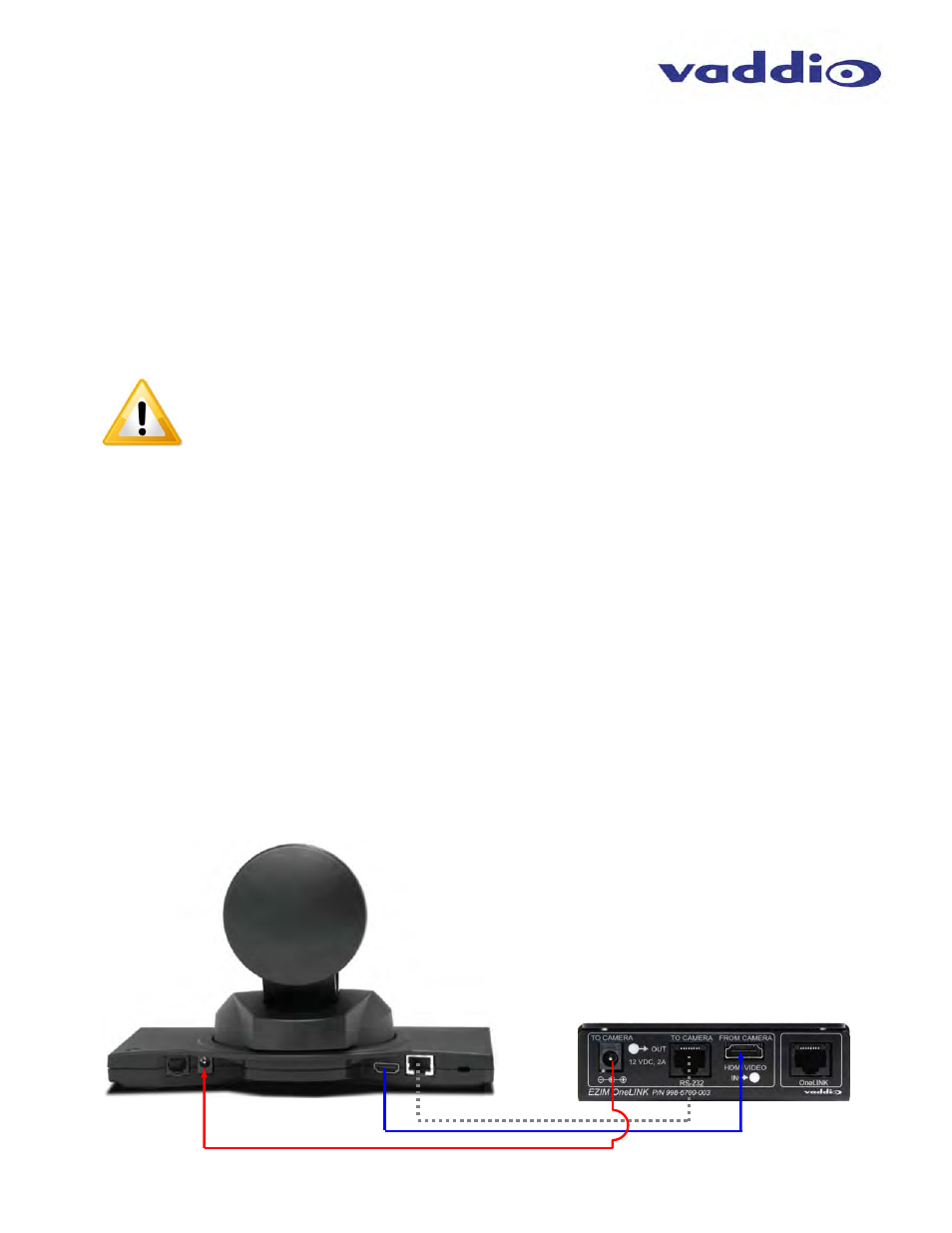
Step 5:
Connect the provided 1’ (30.5cm) cables (HDMI, 5.5mm x 2.1mm and Cat-5e patch cables) to the EZIM and to
the Cisco PrecisionHD camera as shown below.
12VDC
IN
HDMI
OUT
HDMI
IN
RS-232
Connect as Shown using
the Provided Cables
PrecisionHD 720p
Camera Shown