Vaddio DomeVIEW Flush Mount Dome User Manual
Page 6
Vaddio DomeVIEW Flush Mount Dome Installation and User Guide - Document 341-443 Rev C1
Page 6 of 12
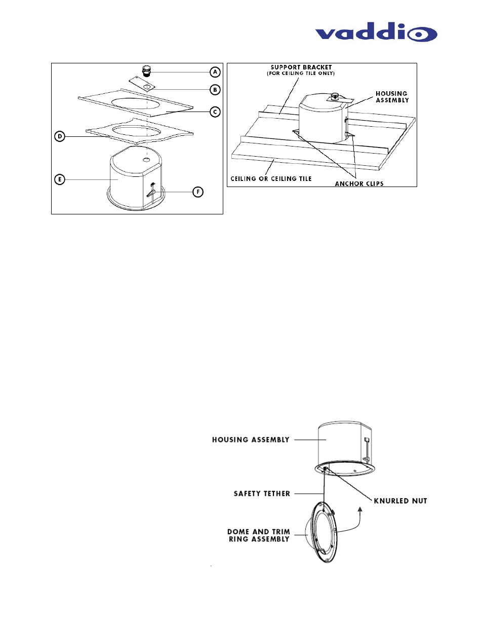
12) Cut an 8” (20.32cm) round hole in ceiling tile (D) or drywall ceiling (See Figure 5).
13) If mounting the enclosure in an acoustic ceiling tile, then the (C) Tile Support Brace (sold separately -
part # 997-9000-000) must be used to hold the weight of the dome enclosure on the back of the Tile
Support Brace and distribute that weight into the ceiling grid. If mounting the enclosure in a drywall
ceiling, then a support brace is not required.
14) Prior to installing the dome back box into the ceiling, pull the required cabling length into the conduit
connector and into the back can to allow easy termination of the camera.
15) Install the Housing Assembly (E) into the ceiling tile or drywall ceiling (Figure 5).
16) Turn the clamp screw clock wise to engage the anchor clip (F) and tighten the Anchor Clips onto the
back of the ceiling or the back of the ceiling Tile Support Brace (C) (Figure 5).
1) When the Camera is securely mounted to the ceiling, take the Dome Bubble and the Twist & Lock White
Trim Ring, (1) in Figure 7, and twist it on to the dome enclosure (two hooks on the trim ring will slide over
the two pegs on the metal enclosure and lock the trim ring and dome into place) to cover the camera. Be
careful to position the safety tether to avoid contact with the PTZ mechanism of the camera.
Figure 5:
Mounting the Flush Mount Enclosure
Figure 6:
Flush Mount Enclosure in the Ceiling
*
(Tile Support Bracket, 997-9000-000, is sold separately for
use with acoustic ceiling tiles. This brace is not needed for
hard/drywall ceilings.)
Figure 7:
Attach the Dome Bubble (Clear is
standard – smoke tinted is
optional) and White Trim Ring.
The assembly has a twist and lock
attachment which provides a
secure connection of the ring to the
back can.
Important Note:
Tuck the safety tether inside the
enclosure to avoid interference to
the PTZ camera movement.
*