Vaddio AutoPresenter User Manual
Page 6
Auto Presenter
AutoPresenter Manual 342-0029 Rev D
Page 6 of 28
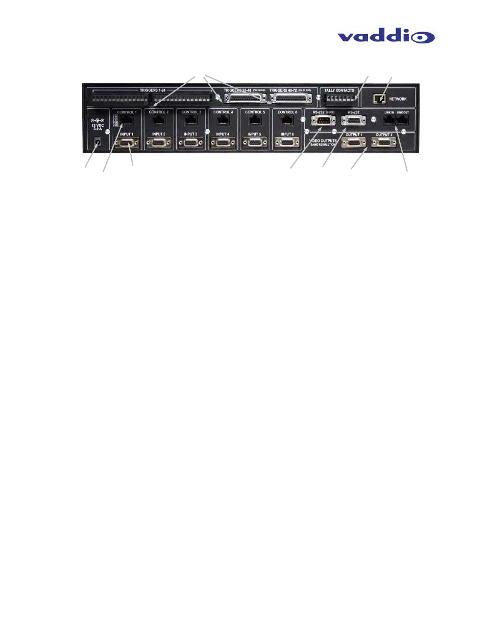
AutoPresenter Back Panel I/O (Figure 3):
11. Trigger Inputs 1 – 24 and Trigger Inputs 25 – 72: The first 24 trigger inputs are on Phoenix-type
connectors. Trigger inputs 1 – 12 can be programmed in First Step, Last Step and Multi Step
operation, which allows the live camera to zoom in or out to multiple trigger positions. Supports
Vaddio AutoVIEW IR, StepVIEW, TouchVIEW, MicVIEW and PresenterPOD trigger inputs as well as
3
rd
party control devices. Trigger inputs 25 - 72 are on two 25-pin connectors.
12. Power Input: AutoPresenter operates on 12 VDC, 3 Amp PowerRite power supply.
13. Control Inputs: For each PTZ camera connected, a homerun CAT-5 cable is run to the RS-232
input of the camera. This allows the pan, tilt and zoom position to be sent to the camera for preset
camera positions. If the input is not a PTZ camera (DVD player, computer, etc.), then this port is not
used.
14. Video Inputs: The video inputs can accept the SD (composite or Y-C), HD (Y, Pb, Pr) or RGBHV
signals (each input is independent and selectable via internal menu). See the Video Resolutions
table at the back of the manual for all supported input/output video signals.
15. RS-232 Thru: The RS-232 Thru connection allows the user to send RS-232 signaling through
AutoPresenter to other control equipment, such as third-party control systems (available on a future
release of firmware) and allows the AutoPresenter to supply the AutoTrak IR Tracking System with up
to six (6) total presets.
16. RS-232: The RS-232 input allows the AutoPresenter to receive commands from third-party
hardware. This port is also used as a connection for updating firmware on the system.
17. Program Outputs: Delivers the same SD (composite or Y-C), HD (Y, Pb, Pr) or RGBHV signal
(selectable via internal menu) on both connectors. See the Video Resolutions table at the back of the
manual for all supported input/output video signals.
18. Link In / Link Out: The Link In / Link Out connectors allow AutoPresenter to seamlessly integrate
with Vaddio’s Precision Camera Controller, when used as an operator controlled seamless switcher.
19. *Network:
The Network port is a 10/100 mbps Ethernet port to allow remote access of the system for
troubleshooting and status (available on a future release of firmware).
20. Tally Outputs: Allows for connecting AutoPresenter to external Tally inputs such as Vaddio’s
PreVIEW HD monitors, Quick-Connect CCU and other third-party tally sources.
* The Network port will be active on a future software release.
Notes:
Vaddio accessory cables for SD (NTSC or PAL composite video) and HD/SD component (YPbPr) are
sold separately. (Part Number 440-5600-000)
Strain relief for the DE-15 (15-pinHD) connectors is highly recommended on the back of the
AutoPresenter for permanent installations to ensure that the cables do not negatively affect the PCB.
⑪
⑳ ⑲
⑫ ⑬
⑭
⑮
⑯ ⑰
⑱