A.J. Antunes & Co BEV-D 9700925 User Manual
General, Warranty information, General specifications
A. J. ANTUNES & CO. www.ajantunes.com 180 Kehoe Blvd., Carol Stream, Illinois 60188
Chill BEV-D iNSTAllATiON iNSTrUCTiONS (P/N 9700925)
1-877-392-7836 Fax: 630-784-1000
Page 1 of 2
P/N 1011075 Rev. B 11/10
General
If you experience any problems with these instructions,
contact the Technical Service Department at 630-784-1000
or toll free in the U.S. at 877-392-7854.
Warranty information
All BEV-D units will be free from defects in materials and
workmanship for a period of three years.
General Specifications
CO2 Water Connections
3/8” (0.95 cm) barbed fittings
with 360° swivel
Sump Water Connections
3/4” (1.91 cm) PVC fittings
Operating Pressure
Max. 150 psi (10.3 kg/cm²)
Electrical Connections
None
installing the BEV-D
To ensure material compatibility, a multipurpose glue for ABS,
PVC, and CPVC must be used. This will ensure a proper bond
between the 3/4” PVC and the black ABS Drain Water Inlet.
The BEV-D is furnished with an assortment of plumbing fittings
and insulating tape to aid in installation. However, due to the
variety of equipment and numerous methods of making connec-
tions, all fittings may not be used.
NOTE: Do NOT attach the soda drip tray line to the BEV-D.
The excess soda in the drip tray should drain separately to
the floor drain. The BEV-D should only be attached to the
cold-plate drain line that contains the melted ice water.
1. Place the BEV-D on its side (horizontally) beneath the ice
bin and attach with the included mounting straps.
NOTE: Due to gravity flow restrictions, the BEV-D must be
mounted entirely beneath the ice bin.
2. Position the BEV-D so the two 3/4” PVC Drain Water Outlets
are oriented in the 12 o’clock and 6 o’clock positions.
3. Glue the PVC plug in the 6 o’clock PVC Drain Water Outlet.
4. Install a PVC drain line from the 12 o’clock Drain Water
Outlet to the floor drain.
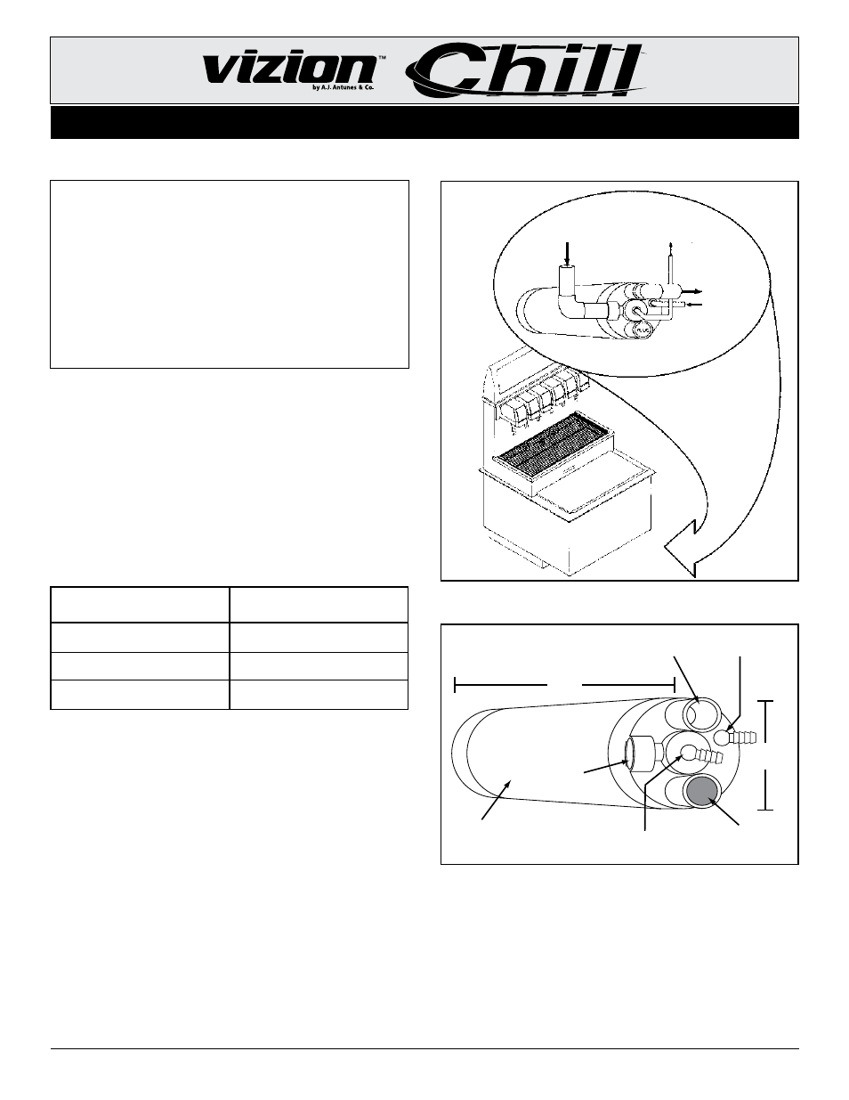
CO
2
Water Inlet
(From Carbonator)
CO
2
Water Outlet
(Insulated Line to
Cold Plate)
Cold Plate
Drain Water Inlet
Drain Water Outlet
to Floor Drain
Figure 1. Typical installation
Figure 2. Specifications Diagram
Drain Water Outlet
< 12 o'clock position >
(To Floor Drain)
CO
2
W ater Inlet
(from Carbonator)
Drain
Water Inlet
(From Cold Plate)
CO
2
W ater Outlet
(To Cold Plate)
Alternate Drain Water Outlet
< 6 o'clock position >
(Insert Plug)
Thermal
Insulation
5.5 inches
(13.8 cm)
17 inches
(42.5 cm)
PLUG
SUGGESTED MATERIALS AND EQUIPMENT NEEDED:
• (10 ft.) 3/4” PVC Pipe
• (4) 3/4” PVC Elbow Fitting
• Multipurpose glue for ABS, PVC, and CPVC
• Tubing Cutter
• PVC Pipe Cutter
• Screwdriver or Drill with Bits
• Channel-Lock Pliers
• Adjustable Wrench
• Measuring Tape
NOTE: Do NOT use copper tubing for the CO2 water line.