Water information – American Dryer Corp. Phase 7 / OPL ensor Activated Fire Extinguishing System D120 User Manual
Page 22
22
JLA Limited
113375 - 6
!
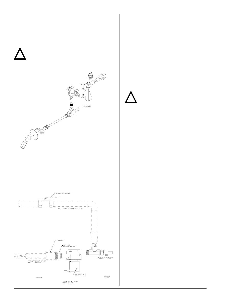
Optional Manual Bypass
Provisions are made in the dryer’s S.A.F.E. system for the
installation of an optional manual bypass. Depending on the model
dryer, the connections for the manual bypass are made at the “T”
or “three way” fitting, located in the outlet supply side of the water
solenoid valve. The use and connections of this manual bypass
are at the option or discretion of the owner.
The water connection for the manual bypass is made
to the “T” or “three way” fitting, which has a 3/8” F.P.T.
and a coupling must be used to provide the minimum
1/2” supply (feed) line.
If the rear area of the dryer, or the water supply is
located in an area where it will be exposed to cold/
freezing temperatures, provisions must be made to
protect these water lines from freezing.
The manual ball cock shutoff valve must be located
outside of the dryer at a distance from the dryer where
it is easily accessible.
Electrical Requirements
No independent external power source or supply
connection is necessary. The 24 volt power to operate
the S.A.F.E. system is accomplished internally in the
dryer (from the dryer controls).
Warning
Electrical power must be provided to the
dryer at all times. If the main electrical
power supply to the dryer is disconnected, the
S.A.F.E. system is inoperative!
S.A.F.E. System Theory of Operation
20-seconds after the heat turns off, the Phase 7 control
monitors the S.A.F.E. system probe located in the top
of the tumbler chamber and records the minimum
temperature. If the minimum recorded temperature is
no less than 120° F (48° C) and the control detects a
35° rise in temperature, this will be the trip point and
the S.A.F.E. system routine will activate.
While a drying cycle is in process and the heat is on,
the Phase 7 control monitors the exhaust temperature
transducer. If the drying cycle temperature set point
is set greater than 160° F (71° C) and the control
detects an exhaust temperature rise 25° F greater than
set point, this will be the trip point and the S.A.F.E.
system routine will activate.
Once the S.A.F.E. system routine is activated, water
will be injected into the tumbler chamber. Anytime
water is being injected into the tumbler; the tumbler
drive will turn the load for 1-second every 15-seconds.
This process will continue for a minimum of 2 minutes.
After 2 minutes has elapsed, the control will check if
the temperature remained above trip point, if so water
will remain on. The control will continue to check if
temperature is above trip point every 30-seconds. If
the water has been on for a constant 10 minutes, the
water will be turned off regardless of the temperature.
If the temperature has dropped below trip point, the
control will turn off the water prior to 10 minutes.
System Reset
After the microprocessor determines that the situation
is under control and shuts the water being injected
into the tumbler off, the microprocessor display will
read “SENSOR ACTIVATED FIRE EXTINGUISHING
ACTIVATED”, and the horn/tone will sound until reset
manually.
To reset the microprocessor and S.A.F.E. system,
press the red key on the keypad.
!
Water Connections
The water connection is made to the 1/2” M.P.T. bushing of the
electric water solenoid valve, located at the rear upper left area of
the dryer. The water solenoid valve has a 3/8” M.P.T. connection
and a 1/2” bushing is supplied to provide the minimum 1/2” supply
(feed) line. Flexible supply line/coupling must be used in effort to
avoid damage to electric water solenoid valve.
Important
Flexible supply line/coupling must be used. Solenoid
valve failure due to hard plumbing connections will
void warranty. It is recommended that a filter or strainer be
installed in the water supply line.
Typical Water Supply …