American Dryer Corp. Phase 7 / OPL ensor Activated Fire Extinguishing System D120 User Manual
Page 15
113375 - 6
Telephone 01422 822282
15
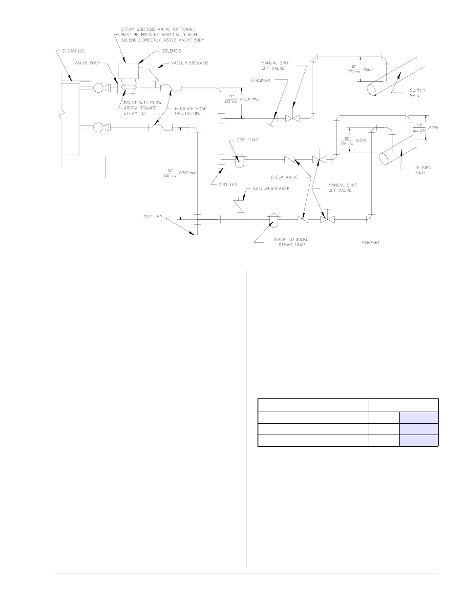
The pressure of the condensate in the steam supply line
will cause water hammer and subsequent heat exchanger
(steam coil) failure. The steam supply connection into the
main supply line must be made with a minimum 12-inch
(30.48 cm) riser. This will prevent any condensate from
draining towards the dryer.
The steam supply line to the dryer must include a 12-inch
(30.48 cm) riser along with a drip trap and check valve. This
will prevent any condensate from entering the steam coil.
Flexible hoses or couplings must be used. The dryer vibrates
slightly when it runs and this will cause the steam coil
connections to crack if they are hard piped to the supply
and return mains.
Shutoff valves for each dryer should be installed in the supply
line, return line, and drip trap return line. This will allow the
dryer to be isolated from the supply main and the return
main if the dryer needs maintenance work.
Install an inverted bucket steam trap and check valve at
least 12-inches (30.48 cm) below the steam coil as close to
the coil as possible.
An inverted bucket steam trap with a capacity of 1,200 lb
(544 kg) of condensate per hour @ 125 psi (8.62 bar) is
required for each unit.
Dryers with optional solenoid valve must be mounted with
coil positioned directly above the valve body.
The supply line and the return line should be insulated. This
will save energy and provide for the safety of the operator
and maintenance personnel.
Water pockets in the supply line, caused by low points, will
provide wet steam to the coil possibly causing steam coil
damage. All horizontal runs of steam supply piping should
be pitched 1/4-inch (6.35 mm) for every 1 foot (0.31 meters)
back towards the steam supply header causing the
condensate in the line to drain to the header. Install a bypass
trap in any low point to eliminate wet steam.
Steam Damper Air System Connections
The dryer is manufactured with a pneumatic (piston) damper
system, which requires an external supply of compressed
air. The air connection is made to the steam damper solenoid
valve, which is located at the rear of the top console.
Air Requirements
Shaded areas are stated in metric equivalents
Air Connection
Air connection to system — 1/4” Quick Connection
No air regulator or filtration is provided with the dryer.
External regulation/filtration of 80 psi (5.51 bar) must be
provided. It is suggested that a regulator/filter gauge
arrangement be added to the compressed air line just before
the dryer connection. This is necessary to ensure that correct
and clean air pressure is achieved.
Compressed Air Supply
Air Pressure
Normal
80 psi
5.51 bar
Minimum Supply
70 psi
4.82 bar
Maximum Supply
90 psi
6.21 bar