Connecting the peripherals – Ampro Corporation Ampro ReadySystem 1U User Manual
Page 8
Chapter 1
Setting Up the ReadySystem 1U
4
Users Guide
ReadySystem 1U
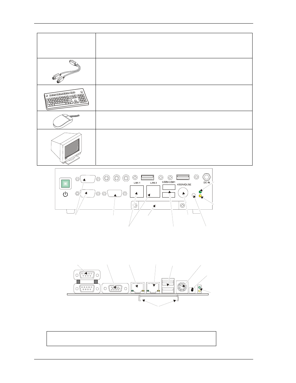
Connecting the Peripherals
7) Connect the Y-cable
and the respective
peripheral cables/
devices
• This includes the Y-cable for the PS/2 keyboard & mouse.
Refer to Figure 1-3 and Table 1-1 for location and description of the
connectors and controls.
• Connect the PS/2 Keyboard & Mouse Y-cable assembly to the
Keyboard/Mouse port on the ReadySystem 1U I/O Panel. See Figure 1-3.
This cable assembly provides two connectors for the PS/2 Keyboard and
PS/2 Mouse shared port with icons for the specific device.
•
Connect the keyboard to the free Y-cable connector with keyboard icon
on it.
• Connect the PS/2 mouse to the Y-cable connector with the respective
mouse icon.
•
Connect the CRT (VGA) monitor through its 15-pin cable to the CRT
(VGA) connector on the I/O Panel of the ReadySystem 1U. See Figure 1-3.
R
d
yS
y1
U
_
03a
LAN1/
LAN2
Power
LED
IDE
Activity
LED
Reset
Switch
Keyboard/
Mouse
Compact Flash
Slot Cover
CRT
(VGA)
COM 1/
COM 2
USB 0/
USB 1
POWER
HDD
RESET
CRT
MIC
LINE IN LINE OUT
COM 2
COM 1
COMPACT FLASH
USB2
USB3
Serial 1 & 2
(Serial 1 Lower)
CRT
Ethernet 1
Ethernet 2
USB 0 & 1
(USB 0 Lower)
Keyboard/
Mouse
Reset
Switch
Power/IDE
Activity
LED
Compact Flash Socket
Typical ReadyBoard (Side view)
Figure 1-3. I/O Panel Controls, Connectors, and Indicators
NOTE
ReadyBoard models with only one Ethernet connector (LAN 1)
have a cover over the LAN 2 Port.