Figure 2-12. installing ide, audio, and usb cables – Ampro Corporation Ampro ReadySystem 1U User Manual
Page 22
Chapter 2
Installing ReadySystem 1U Options
18
Users Guide
ReadySystem 1U
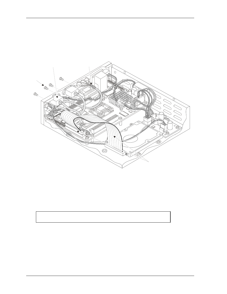
4. Connect the IDE cable to the IDE connector (J22). See Figures 2-9, 2-10, and 2-12.
♦
If you did not disconnect the IDE cable from the hard disk drive earlier, just connect the free
end of the IDE cable to the IDE connector (J22) on the ReadyBoard.
♦
If you also disconnected the IDE cable from the hard disk drive (HDD) earlier, then re-
connect it to the IDE connector on the HDD. The red strip on the cable should match with
pin-1 on the HDD and is typically located next to the jumper settings on the HDD. See
Figure 2-12.
Rd
yS
y1
U_
16
ab
IDE Cable
USB2 and USB3
Cable
M3x0.5
Screws (4)
Audio In/Out
Cable
Figure 2-12. Installing IDE, Audio, and USB Cables
5. You may replace the top cover before restoring power to check the ReadySystem 1U operation,
or restore power to check system operation before replacing the top cover to the enclosure.
In either case, observe all safety precautions when replacing the top cover or restoring power to
the system.
6. Follow the power-on procedures outlined in Chapter 1 to restore power to the ReadySystem.
CAUTION
Depending on BIOS Setup, some ReadyBoard products will power
on as soon as you connect live DC power to the system.