Ampro Corporation Ampro ReadySystem 1U User Manual
Page 18
Chapter 2
Installing ReadySystem 1U Options
14
Users Guide
ReadySystem 1U
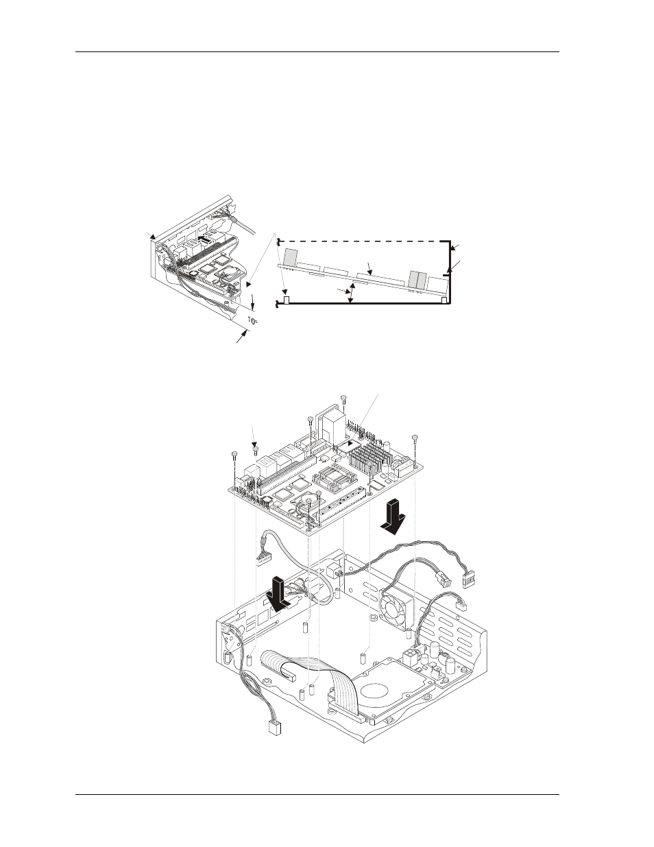
7. Position the ReadyBoard near the eight standoffs on the enclosure base at about a 10
° angle to the
mounting surface. See Figures 2-7 and 2-8.
8. Insert the ReadyBoard and its LAN connectors just under the lip of the LAN port on the
enclosure wall, behind the I/O panel. See Figure 2-7.
9. Slowly work the ReadyBoard into place, inserting the I/O connectors and LEDs into the
respective openings on the I/O Panel.
When you have the ReadyBoard in position you should clearly see the mounting holes for the
eight standoffs under the board mounting holes, and the LEDs should fit into the openings
provided on the I/O Panel.
R
d
yS
y1U
_1
1a
LAN Port
Lip
I/O Panel
ReadyBoar
d
10 Angle
°
ReadyBox 1U
Left Side View
LAN1
I/O Panel
Insert ReadyBoard
into enclosure just
above standoffs
ReadyBox 1U
Right Side View
Figure 2-7. ReadyBoard Positioned Under LAN Ports
R
d
yS
y1U
_1
2b
b
M3x0.5 Screws (8)
6 mm Thread Length
with washers and
lock washers
ReadyBoard
Note: All standoffs have a
thread size of M3x0.5
and accept M3x0.5 screws.
Figure 2-8. Installing ReadyBoard into Enclosure