Ampro Corporation Ampro ReadySystem 1U User Manual
Page 32
Appendix B
System Overview
28
Users Guide
ReadySystem 1U
R
d
yB
x1
U
_03a
DC IN
USB2 and USB3
Audio Connectors
Momentary
Power Switch
POWER
HDD
RESET
CRT
MIC
LINE IN LINE OUT
COM 2
COM 1
COMPACT FLASH
USB2
USB3
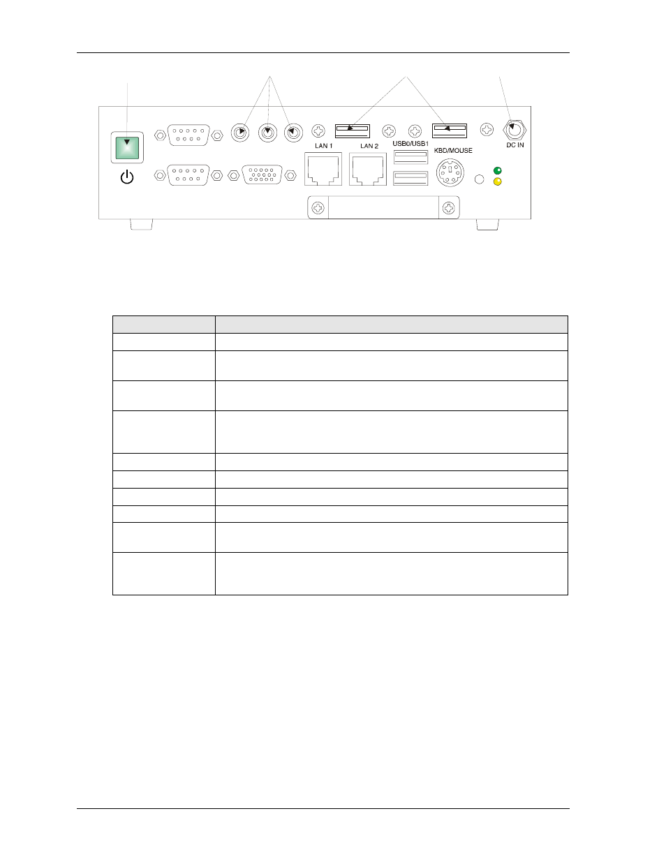
Figure B-3. I/O Panel Controls and Connectors (Front view)
Table B-2 describes the I/O panel access openings for connector, control, or indicators provided with the
ReadyBoard SBC shown in Figure B-4.
Table B-2. Connectors or Control/Indicator I/O Panel Openings
Access Opening
Description
Power-On LED
This power-on indicator is provided on the ReadyBoard.
HDD Activity LED
This IDE activity indicator shows when there is I/O activity for the IDE hard
drive or compact flash card and is provided on the ReadyBoard.
Reset Switch
This reset switch is provided on the ReadyBoard. Pressing the Reset switch
supplies a ground signal on the reset line causing a hard reset.
Keyboard/Mouse
This 6-pin single PS/2 Keyboard/Mouse connector is provided on the
ReadyBoard. It requires a dual PS/2 output cable provided in the ReadyBoard
SBC QuickStart kit.
USB 0 & 1
These two 4-pin USB type A connectors are provided on the ReadyBoard.
LAN 1 (Ethernet 1)
This 8-pin (RJ45) connector is provided on the ReadyBoard.
LAN 2 (Ethernet 2)
This 8-pin or 10-pin (RJ45) connector is provided on the ReadyBoard.
Video (CRT VGA)
This 15-pin (DB15) connector is provided on the ReadyBoard.
COM 1 & COM 2
(Serial 1 & Serial 2)
These two 9-pin (DB9) connectors are provided on the ReadyBoard.
Compact Flash
Socket
The compact flash socket (not shown) is provided on the underside of the
ReadyBoard and accepts the compact flash card, if installed, through the
opening at the bottom of the I/O panel of the ReadyBox 1U.