Ampro Corporation Ampro ReadySystem 1U User Manual
Page 15
Chapter 2
Installing ReadySystem 1U Options
ReadySystem 1U
Users Guide
11
R
d
yS
y
1
U
_07ab
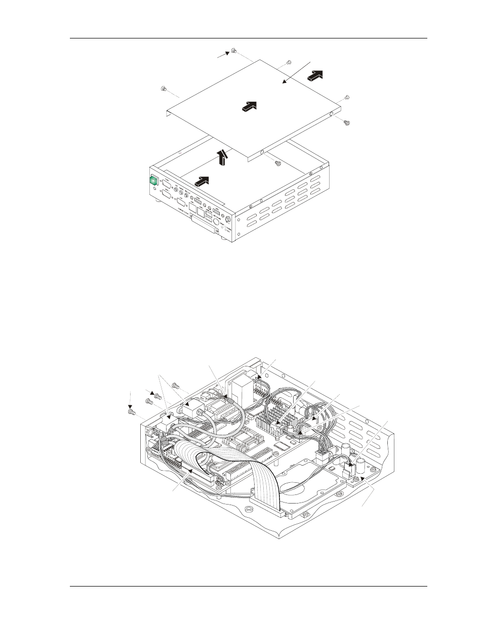
Remove Top Cover
M3x0.5 Screws (6)
Figure 2-3. Removing ReadySystem Top Cover
5. If necessary, remove or loosen the four screws holding the two USB cables (USB 2 & USB 3) to
the enclosure I/O Panel. See Figure 2-4.
You might be able to just loosen the two USB connectors (USB 2 & USB 3) to free the
ReadyBoard from the enclosure because of the tight fit between the two USB connectors and the
tops of the Ethernet ports. If not, you will have to remove the two USB connectors (USB 2 &
USB 3) from the enclosure. See Figure 2-4.
6. If necessary, remove the two USB cables (USB 2 & USB 3) connected to the enclosure I/O Panel.
See Figure 2-4.
R
d
yS
y1U
_8ab
Loosen or remove the
USB2 and USB3 connectors.
M3x0.5
Screws (4)
Audio In/Out
Power Switch
Power In
Power-On
+5V Regulator
Board
Enclosure Fan
Primary IDE
DC In
Figure 2-4. Removing USB Connectors