Mounting and cover location – Ampro Corporation Ampro ReadySystem 1U User Manual
Page 38
Appendix B
System Overview
34
Users Guide
ReadySystem 1U
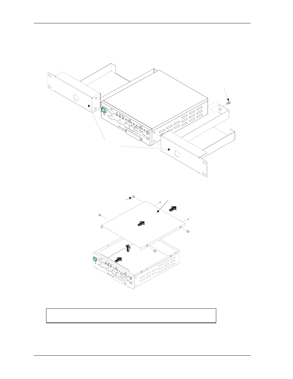
Mounting and Cover Location
Figures B-11 and B-12 provide an illustration of the optional rack mounting and an illustration of the top
cover location. The four optional plastic feet with screws are also shown in Figure B-12.
R
d
yB
x1U
_02b
a
1/4 - 20 UNC Screws (6)
Rackmount Sides (2)
(Left & Right)
Figure B-11. Rack Mounting Hardware
R
d
yB
x1U
_14a
b
Remove Top Cover
M3x0.5 Screws (6)
Figure B-12. Removing Top Cover
NOTE
Slide the top cover to the rear as shown in Figure B-12 before
lifting the top cover off the enclosure.