I/o panel description, Table b-1. installed connectors or controls – Ampro Corporation Ampro ReadySystem 1U User Manual
Page 31
Appendix B
System Overview
ReadySystem 1U
Users Guide
27
R
d
yB
x1U
_
02a
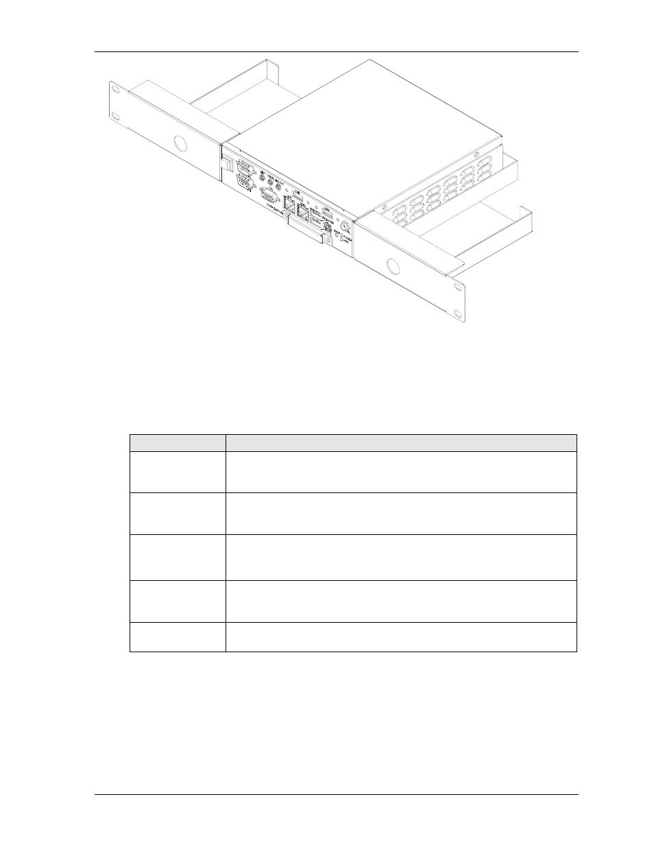
Figure B-2. Optional Rack-Mount Hardware (Installed)
I/O Panel Description
Table B-1 describes the connectors or controls on the I/O panel provided with the ReadyBox 1U shown
in Figure B-3.
Table B-1. Installed Connectors or Controls
Control/Connector Description
Power Switch
This momentary push button Power Switch controls DC power and has an
internal cable and connector. The integrator must connect the 2-wire, 5-pin
connector to the ReadyBoard at the Utility connector.
DC IN
This 2-pin coaxial connector is connected to the internal DC regulator and
accepts 12 or 24 VDC, +/- 5% from an AC-to-DC converter (brick power
supply).
Audio:
MIC, Line In,
Line Out
These two 3-pin connectors and one 2-pin connector (MIC) with respective
cable are provided with the ReadyBox 2U. The integrator must connect the
cable to the Audio In/Out connector on the ReadyBoard.
USB 2 & 3
These two 4-pin connectors with the respective cable are provided with the
ReadyBox 1U. The integrator must connect the cable to the ReadyBoard USB
header.
Compact Flash
Cover and Slot
This compact flash cover and slot (not shown) protects the compact flash card
if installed, and ensures good EMI shielding for the ReadyBox 1U.