PerTronix Flame-Thrower VW Billet Distributors User Manual
Page 2
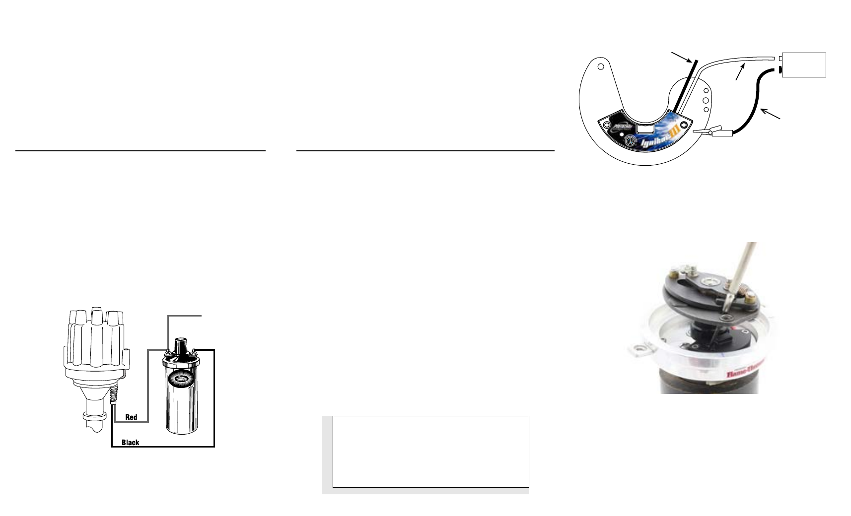
Red Wire
Jumper Wire
Black Wire (Open)
Switch
+
-
To Ignition
distributor housing. The clamp should sit flat against the distributor
collar.
3. Remove the Flame-Thrower distributor cap.
4. Turn the distributor drive tang so that it lines up with the distributor
drive shaft slot.
5. Set the distributor into the engine. The distributor hold-down should
sit completely flat on engine block.
6. Place the distributor cap onto the housing.
7. Turn the housing so that the terminal, that represents the first
cylinder in the firing order, lines up with the rotor contact terminal.
WIRING
The Flame-Thrower III billet distributor can be used in conjunction
with most ignition coils rated at 0.32 ohms or greater. For optimum
performance we recommend our Flame-Thrower III canister style or HC
e-core coil.
Many vehicles came equipped with ballast resistors or resistance wires.
To achieve optimum performance we recommend removal of these
components. Determine the proper wire length, and attach the provided
terminals. (Use a wire crimping tool to achieve an adequate connection).
1. Attach the
Red wire to the coil positive terminal or a 12-volt ignition
source. See Figure B.
2. Attach the
Black wire to the coil negative terminal.
3. Check to insure correct polarity and that all connections are tight.
4. Reconnect the battery negative cable.
REV-LIMITER SPECIFICATIONS
Settings
RPM’S
Minimum
4000
Maximum
9000
Factory Setting
5500
REV-LIMITER SETTING PROCEDURE
Note: It’s recommended that the Rev-Limiter be set to your
desired setting before installing the distributor. Note: The
Ignitor III Rev-Limiter is preset at 5500 RPM’s. Setting the rev
limit may be done effectively and easily on a bench or table.
•
Connect the module to a 9-volt battery as shown in figure C. Then follow the
setting procedure outlined below.
1. Remove distributor cap and rotor.
2. Line up the round or square hole on the advance plate to the Rev-Limiter
adjustment screw. See Figure D.
3. Turn the ignition key to the ‘ON’ position. Do not try starting the engine.
4. Turn the Rev-Limit dial clockwise until it stops. Turn the dial counterclockwise until it
stops. A slow blinking of the LED indicates that the setting procedure has been initial-
ized and that the Rev-Limit can be set.
5. Turning the dial clockwise sets the Rev-Limit. After turning the dial, pause and watch
the LED for verification of the Rev-Limit setting. Long flashes indicate 1000 RPM’s
and short flashes indicate 100 RPM’s. For example, 6 long flashes followed by 2 short
flashes means the Rev-Limit is 6200 RPM’s. Continue turning the Rev-Limit dial until
the desired Rev-Limit is reached.
NOTE: Leaving the Rev-Limit dial in the full counterclockwise position disables
the Rev-Limiter.
6. Let the LED sequence thru at least three complete cycles. This verifies the correct set-
ting and prepares the unit for permanent storage of the Rev-Limit.
7. Turn the ignition key off, this signifies to the Ignitor III that the Rev-Limit procedure is
complete.
Note: The Ignition key MUST be turned off or the engine will not start.
8. Your rev limit is now set and will not change until you go through this procedure again.
9. Re-install cap and rotor.
9 Volt
Battery
+
-
Figure C
Figure B
Figure D
8. Tighten the hold down and slightly tighten the distributor clamp. Once
the ignition timing is adjusted the distributor clamp should be tightened
completely.
Note: Hold down clamp must be free of paint and corrosion,
this will insure that a proper ground is made to the engine block.
9. Clip down the distributor cap and install the spark plug wires in the
proper firing order. Beginning with the number one cylinder move
clockwise 1 - 4 - 3 - 2.
10. See wiring instructions.
WARNING!!! DO NOT USE WITH SOLID CORE SPARK
PLUG WIRES OR COIL WIRE.