Figure 1, Figure 2 – PerTronix Flame-Thrower Billet Slip Collar Distributor User Manual
Page 2
-!.)&/,$
%.').%
",/#+
/),
-%!352%
FiGuRe 1
Remove the Flame-Thrower billet distributor cap.
1.
Install the distributor gasket over the gear, and up to the distributor collar. Use a
2.
small amount of gasket adhesive to help hold the gasket in place.
Lubricate the distributor gear and distributor shaft with clean engine oil.
3.
Turn the shaft so that when the distributor is placed into the engine, the rotor posi-
4.
tion matches that of the original distributor. As the distributor drops down, the rotor
will turn slightly as it engages with the camshaft gear. Adjust for this rotation by
turning the rotor a few degrees prior to the gear engagement. Several attempts
may be necessary to achieve the proper rotor position. The distributor collar should
sit completely flat on the intake manifold or block.
Place the distributor cap onto the housing.
5.
Turn the housing so that the terminal, that represents the first cylinder in the firing
6.
order, lines up with the rotor.
Install the distributor hold down and tighten the hold down bolt slightly. Once the
7.
ignition timing is adjusted the hold down bolt should be tightened completely.
Tighten the cap into place and install the spark plug wires in the proper firing
8.
order.
DiStRiButOR inStAllAtiOn
Locate the vacuum hose that was previously attached to the vacuum advance can-
9.
ister. This hose should originate at a ported vacuum source. For Vacuum advance
distributors: Temporarily plug the end of this hose to allow proper timing. After set-
ting initial timing the hose will be unplugged and attached to the vacuum advance
on the distributor. For Non-vacuum advance distributors: remove the vacuum hose
and plug the vacuum port.
DiStRiButOR inStAllAtiOn COnt.
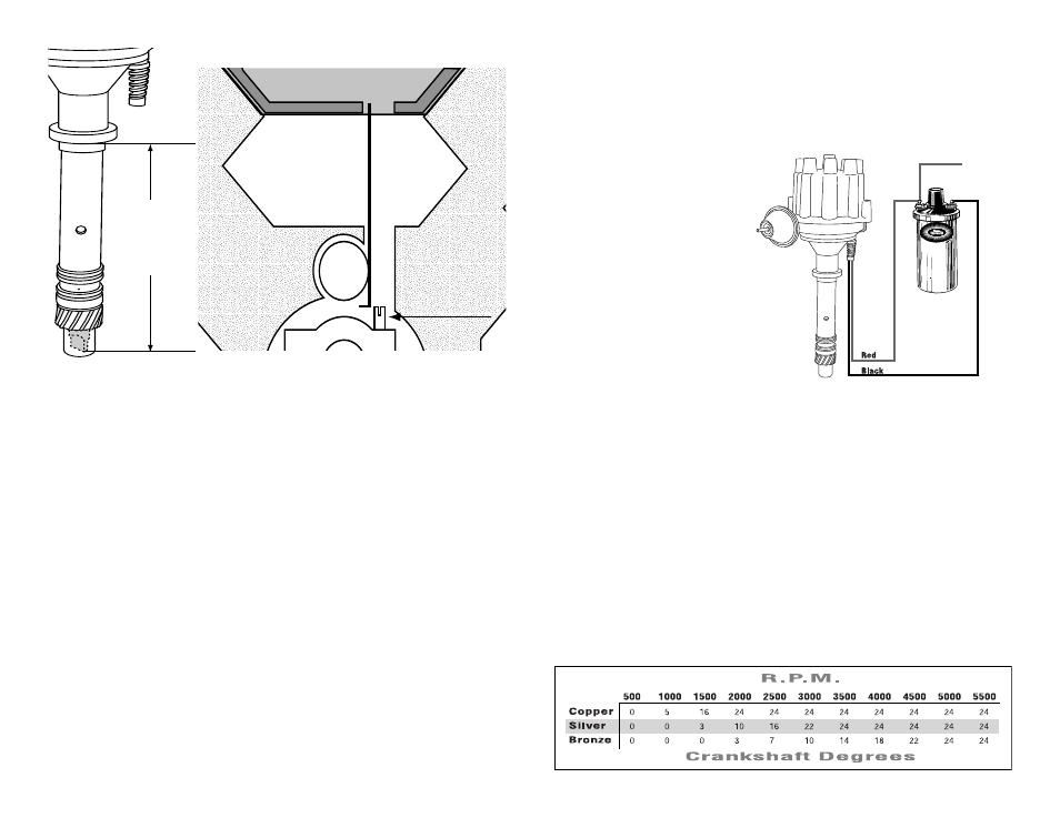
The Flame-Thrower billet distribu-
tor can be used in conjunction with
most ignition coils rated at 0.45
ohms or greater. For optimum
performance purchase and install
a Flame-Thrower II or HV E-Core
high performance coil.
Many vehicles came equipped
1.
with ballast resistors or resis-
tance wires. To achieve opti-
mum performance we recom-
mended removal of these com-
ponents.
Determine the proper wire
2.
length, and attach the provided
terminals. (Use a designated wire
crimping tool to achieve an adequate connection)
Attach the Red wire to the coil positive terminal or a 12-volt ignition source.
3.
Attach the Black wire to the coil negative terminal.
4.
Check to insure correct polarity and that all connections are tight.
5.
Reconnect the battery negative cable.
6.
+
-
To Ignition
wiRinG
Start the engine and set the initial timing.
1.
Tighten the distributor hold down.
2.
For vacuum advance distributors, connect the vacuum hose to the vacuum
3.
advance canister.
To adjust the mechanical advance curve, elect the appropriate springs from the
1.
chart below. The Flame-Thrower billet distributor is factory equipped with the
silver springs.
Remove the cap and rotor.
2.
Remove the existing springs and install the desired springs.
3.
Reinstall the rotor and cap.
4.
FinAl ADJuStMentS
MeCHAniCAl ADVAnCe ADJuStMentS
This procedure is recommended to insure proper gear mesh between the cam gear
and the distributor gear.
Procedure: Coat the distributor gear with moly grease and install the distributor. Next,
crank the engine over several times. Before removing the distributor, ensure that the
rotor position is line up with the original removal mark. Remove distributor and inspect
the gear pattern shown on the grease. The proper mesh will leave an even pattern in
the middle of the gear. Adjust the slip collar if needed to correct the gear mesh.
CHeCKinG GeAR MeSH
-%!352%
"/44/-
&,!.'%
4!.'
FiGuRe 2