Addonics Technologies RCHDSAES User Manual
Page 2
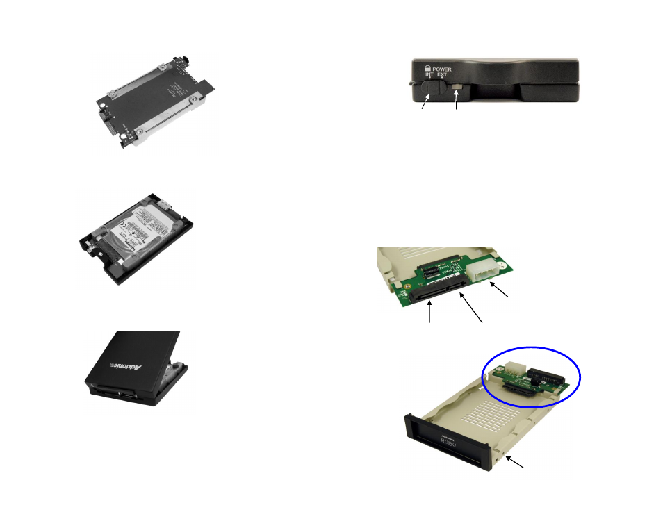
Step 4 Turn over the PCB and secure the hard drive to the PCB with the
mounting screws that come with the kit.
Step 5 Mount the board to the bottom cover.
Step 6 Put the top cover on by holding it in near vertical position and sliding the
two metal clips inside the two small slots on the rear of the bottom cover.
Step 7 Lower the front of the top cover and making sure the two covers lined up
properly. Tighten the small retaining screw on the front of the bottom cover to
close the enclosure.
Ruby Enclosure
Switch:
INT: This mode is used when the enclosure is placed inside a drive
cradle. For mobile rack kits, this is the mode used.
EXT: This mode is used if the enclosure is used as an external hard
drive.
Ruby Drive Cradle
Note: You can only use one power connector at a time. Either use the 4-pin
Molex or 15-pin SATA connector but not simultaneously use them.
Mounting holes for
3 ½” drive bay
15-pin SATA
power connector
4-pin Molex
power connector
Power LED and
Drive Access LED
Switch
7-pin SATA
data connector