Redundant power supply front view, Leds, Table 1: atrps1000 leds – Allied Telesis AT-RPS1000 User Manual
Page 4
AT-RPS1000 Installation
2
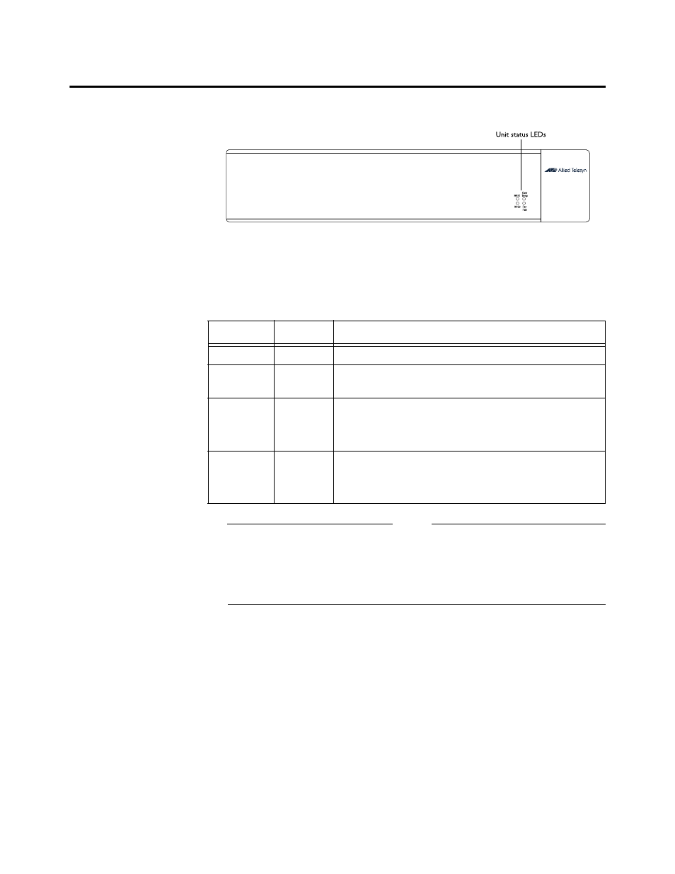
Redundant Power Supply Front View
Figure 1 shows the front panel view of the AT-RPS1000.
Figure 1: Redundant Power Supply Front Panel
LEDs
Table 1 describes the LED behavior on the AT-RPS1000.
NOTE
If the AT-RPS1000 DC cables are not connected to a gigabit switch, but
the AC power cords are connected to an AC outlet, the RPS1 and RPS2
LEDs will blink. If one of the cables is properly connected to a gigabit
switch, but the remaining cable is not, the unconnected cable will cause
its associated AT-RPS1000 LED to blink.
Table 1: AT-RPS1000 LEDs
LED
Color
Indicates
RPS 1
Green
The first redundant power supply is powering a gigabit switch.
RPS2
Green
The second redundancy power supply is powering a gigabit
switch.
OVER
TEMP
Off
Yellow
The AT-RPS1000 temperature is normal.
The AT-RPS1000 is indicating an overheat condition (>60
degrees Celsius).
FAN FAIL
Off
Yellow
The AT-RPS1000 fan is operating properly.
The AT-RPS1000 fan speed has slowed to 80 percent or less of
full rotational speed and should be replaced.