Switch leds – Allied Telesis AT-9006LX/SC User Manual
Page 19
AT-9006 Quick Install Guide
9
Switch LEDs
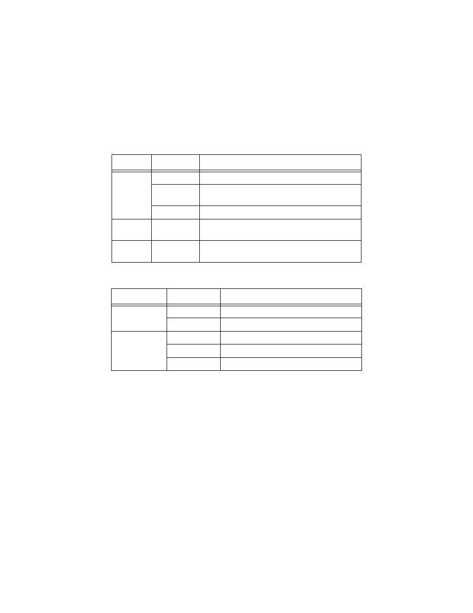
Table 2 and Table 3 describe the functions of the LEDs on the Ethernet
switch.
Table 2 Power and Fault LEDs
Table 3 Port LED Status
For information on troubleshooting the switch, refer to the AT-9006SX/SC
and AT-9006LX/SC Installation Guide.
LEDs
State
Description
Fault
Solid Red
The switch or management software is malfunctioning.
Flashing Red
The switch is booting, running diagnostic tests, writing
images to FLASH, or transferring files using XMODEM.
OFF
Normal operation.
RPS
Solid Green
The RPS is connected to the switch. To verify that the
RPS is operating correctly, refer to your RPS manual.
Power
Solid Green
The switch is receiving power, voltage is within the
acceptable range, and the power supply is working.
LEDs
State
Description
Link/Activity
Solid Green
This indicates a link.
Flashing Green
This indicates activity.
Duplex/Collision
Solid Green
The port is operating at full-duplex.
Solid Amber
The port is operating at half-duplex.
Flashing Amber
Collisions are occuring on the line.