Installing the switch, Verifying the package contents, L /a d/c – Allied Telesis AT-9006LX/SC User Manual
Page 12: Class 1 laser product do not stare into beam
2
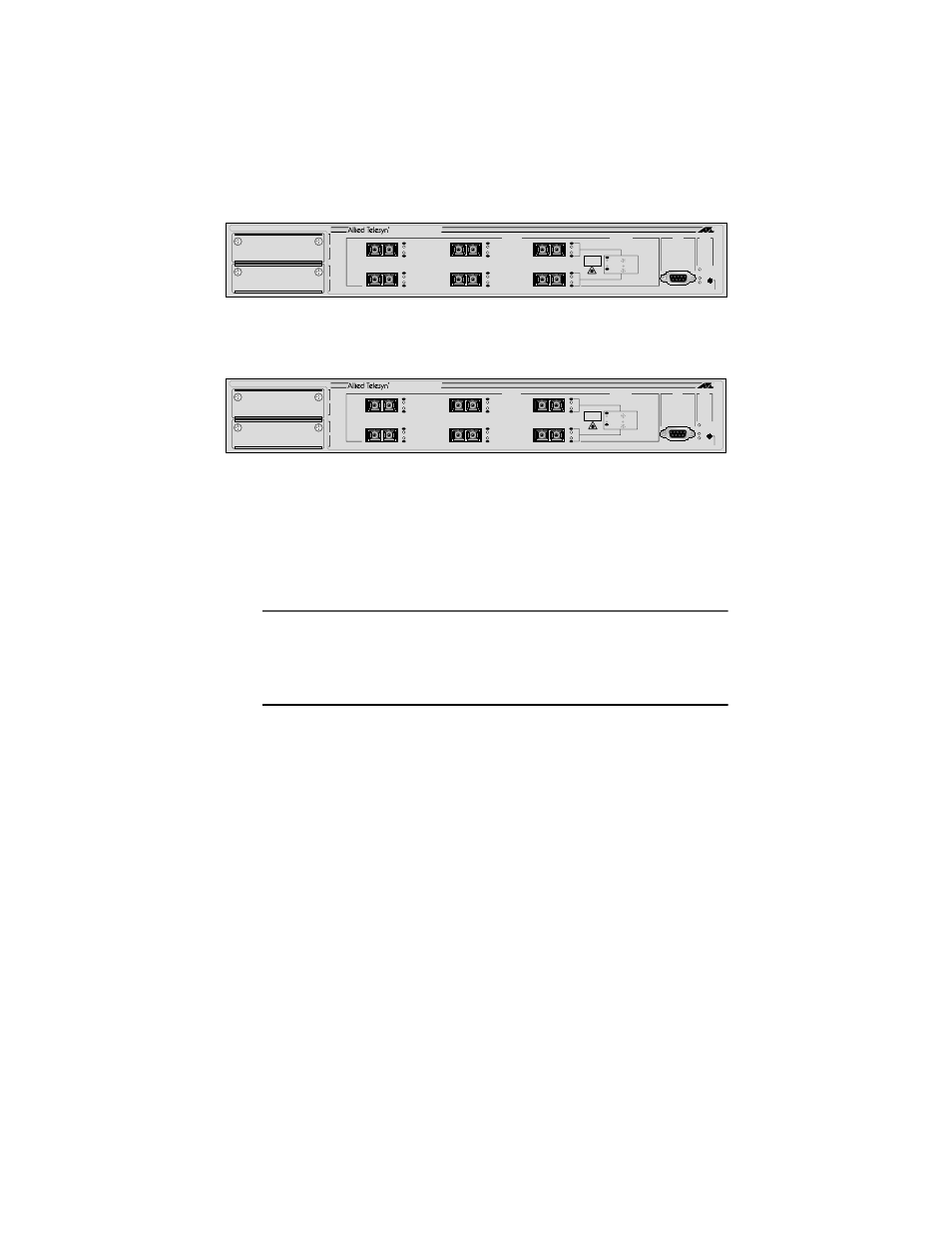
Figure 1 shows the front panel of the AT-9006SX/SC switch.
Figure 1 AT-9006SX/SC Front Panel
Figure 2 shows the front panel of the AT-9006LX/SC switch.
Figure 2 AT-9006LX/SC Front Panel
Installing the Switch
The following sections explain how to install the Ethernet switch in your
network.
Note
For information on site requirements, cabling specifications, and
network topologies, refer to the AT-9006 Ethernet Switch Installation
Guide. This guide is available on the Allied Telesyn web site at
www.alliedtelesyn.com.
Verifying the Package Contents
Make sure the following components are included in the switch package. If
any of these items are missing or damaged, contact your sales representative.
"
One AT-9006 switch
"
Two mounting brackets
"
Six flathead Phillips screws
"
Power cord (Americas, EC, Australia, and UK only)
"
This Quick Install Guide
"
Warranty card
STATUS
RESET
FAULT
RPS
PWR
1000BASE-SX
A
B
RS-232
TERMINAL PORT
PORT ACTIVITY
L /A
D/C
L /A
D/C
L /A
D/C
L /A
D/C
L /A
D/C
L /A
D/C
LINK
ACTIVITY
FULL DUP
L /A
D/C
HALF DUP
COL
1
RX
TX
4
RX
TX
2
RX
TX
5
RX
TX
3
RX
TX
6
RX
TX
AT-9006SX/SC
1000BASE-SX GIGABIT ETHERNET SWITCH
CLASS 1
LASER PRODUCT
DO NOT STARE
INTO BEAM
STATUS
RESET
FAULT
RPS
PWR
1000BASE-SX
A
B
RS-232
TERMINAL PORT
PORT ACTIVITY
L /A
D/C
L /A
D/C
L /A
D/C
L /A
D/C
L /A
D/C
L /A
D/C
LINK
ACTIVITY
FULL DUP
L /A
D/C
HALF DUP
COL
1
RX
TX
4
RX
TX
2
RX
TX
5
RX
TX
3
RX
TX
6
RX
TX
AT-9006LX/SC
1000BASE-SX GIGABIT ETHERNET SWITCH
CLASS 1
LASER PRODUCT
DO NOT STARE
INTO BEAM