Pinout assignments – Allied Telesis AT-FS717FC/xx User Manual
Page 33
AT-FS713FC/xx and AT-FS717FC/xx Series Installation Guide
23
Table 10 Fiber Optic Loss Specification (Benchmark)
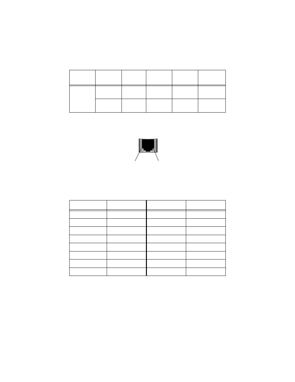
Pinout Assignments
Figure 6 shows the pin assignments of the RJ-45 connector.
Figure 6 RJ-45 Pin Assignments
Table 11 lists the 10/100Base-TX connector pins and their signals when the
port is operating in either MDI or MDI-X configuration.
Table 11 RJ-45 Pinouts
Fiber Type
Fiber Optic
Diameter
Optical
Frequency
Typical Loss
Factor
Worst Case
Loss Factor
Bandwidth
Multimode
50/125
microns
1310 nm
1.00 dB/km
1.50 dB/km
400 Mhz-km
62.5/125
microns
1310 nm
1.00 dB/km
1.50 dB/km
500 Mhz-km
MDI-X (Default)
Signal
MDI
Signal
1
RX+
1
TX+
2
RX-
2
TX-
3
TX+
3
RX+
4
-
4
-
5
-
5
-
6
TX-
6
RX-
7
-
7
-
8
-
8
-
Pin 1
Pin 8
This manual is related to the following products: