Ethernet hub workgroup topology – Allied Telesis AT-FS717FC/xx User Manual
Page 19
AT-FS713FC/xx and AT-FS717FC/xx Series Installation Guide
9
Ethernet Hub Workgroup Topology
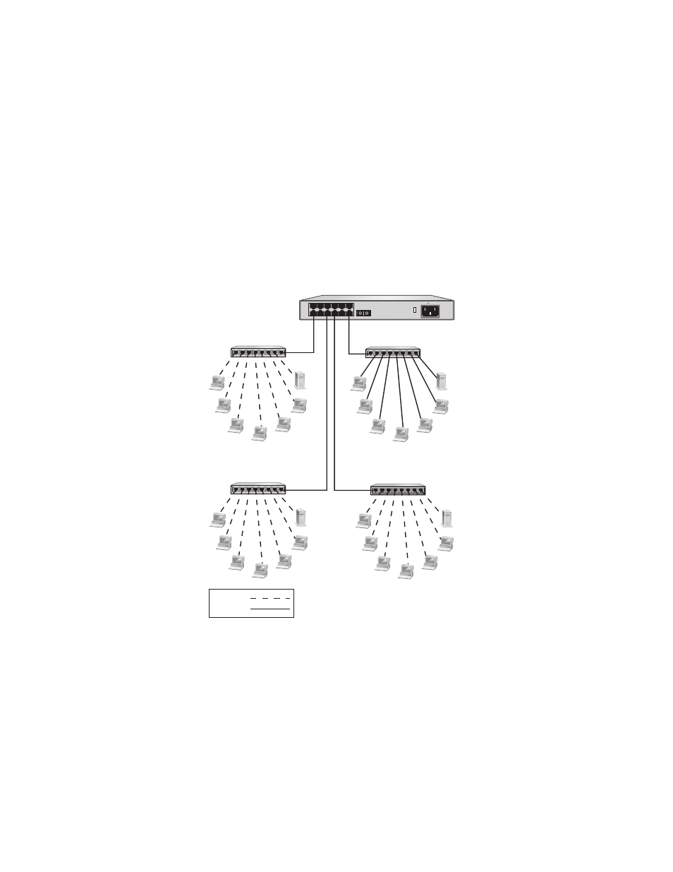
Figure 4 illustrates an Ethernet hub workgroup topology where an
AT-FS713FC/SC is used to connect together four 10/100 Mbps Ethernet hubs.
This allows the switch to function as a bridge between the different
workgroups by controlling the flow of data between the workgroups. The
switch transfers an Ethernet frame from hub-to-hub only when the
destination end-node for the frame is on a different hub than the end-node
that originated the frame. This reduces the amount of unnecessary data traffic
in each workgroup. This frees up bandwidth and improves network
performance.
Figure 4 Ethernet Hub Workgroup Topology
1
3
5
7
9
11
T X
R X
2
4
6
8
10
12
13
120-240V 50-60Hz 0.5A
5
4
3
2
1
6
7
8
5
4
3
2
1
6
7
8
5
4
3
2
1
6
7
8
5
4
3
2
1
6
7
8
AT-FS713FC/SC
Ethernet Hub
Ethernet Hub
Ethernet Hub
Ethernet Hub
100 Mbps
10 Mbps