Switch blade 4000, Switch blade – Allied Telesis SWITCHBLADE POWER SUPPLY UNIT User Manual
Page 7
Quick Install Guide
7
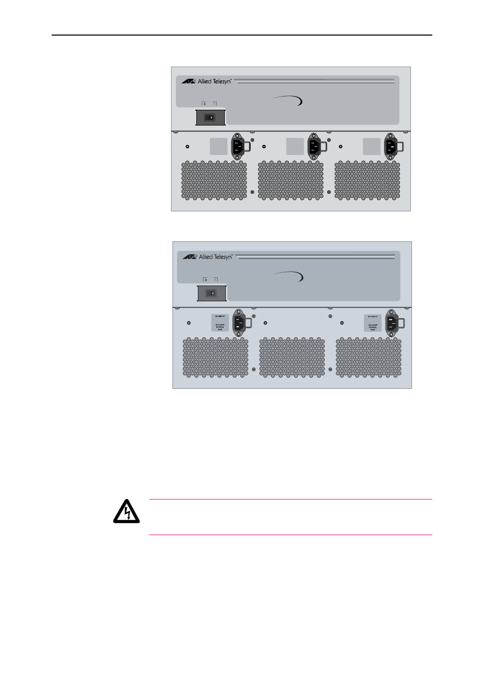
Figure 3: AC power connectors on a CH8 with triple power inlets.
Figure 4: AC power connectors on a CH8 with dual power inlets.
For DC Models:
Read the
Safety and Statutory Information booklet before connecting a
SwitchBlade PSU to a DC power source. A copy of the safety booklet is
included with each PSU. A PDF version is included on the Documentation and
Tools CD-ROM shipped with every switch controller and every chassis, or can
be downloaded from www.alliedtelesyn.co.nz/support/switchblade/.
Only trained and qualified personnel should connect a DC power supply. Due
to exposed terminals, DC powered SwitchBlades should only be installed in
Restricted Access Areas.
DC supply cable specifications:
• Three core cable is required. Where the unit is powered by a
centralised DC power, a UL listed tray cable should be used to connect
to this power source.
•
Minimum core size: 3.3 mm
2
(12 AWG) for chassis type AT-SB4104-80,
and 8.4 mm
2
(8 AWG) for the chassis type AT-SB4108-80.
•
Minimum cable rating: 600V, 90 degrees Celsius.
DC power supply specifications:
•
40-60 V DC, 48 V DC nominal.
AC INPUT
100-240V
8.0-4.0A
50-60Hz
AC INPUT
100-240V
8.0-4.0A
50-60Hz
AC INPUT
100-240V
8.0-4.0A
50-60Hz
RESET
RUN
STANDBY
SwitchBlade
4000
RESET
RUN
STANDBY
SwitchBlade
4000