Allied Telesis SwitchBlade Line Card User Manual
Page 7
Quick Install Guide
7
C613-04030-01 REV H
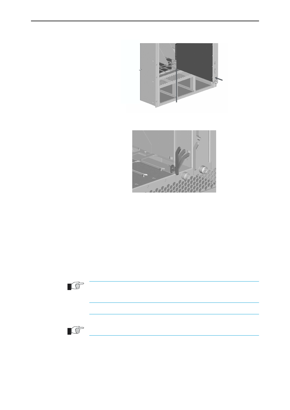
Figure 3: Card guides on the SwitchBlade 8 chassis.
Figure 4: Ejector lever and locking slot.
7.
Secure the line card
Move the ejector levers to the locked position and tighten the line card’s
two Phillips screws (see Figure 2 on page -6).
If the chassis is receiving power, one or more L/A LEDs will light amber
when the line card is correctly installed. The LED(s) will remain lit until the
card is configured.
8.
For cards that accept miniature pluggable transceivers, such as GBICs, SFPs and
XFPs, install the transceivers.
Slide each transceiver into its appropriate slot and press it firmly into
place.
A range of pluggable transceivers have been tested and approved for use with the
SwitchBlade. Contact your authorised Allied Telesyn distributor or reseller for more
information, or visit www.alliedtelesyn.co.nz.
In order to connect each fibre into its correct terminal, check which terminal is the
“Send” and which is the “Receive” by reading the marking on each GBIC before
inserting it into its card socket.
9.
Connect the data cables
Make sure each cable connection is secure.
bottom card guide
Extractor lever