Installation and safety guide 5, Card guide – Allied Telesis Uplink Module User Manual
Page 5
Installation and Safety Guide
5
613-000689 Rev A
5. Prepare the uplink module.
In an antistatic environment, remove the uplink module from its packing
material. Be sure to observe ESD precautions.
Warning Do not attempt to install an uplink module or any other expansion
option without observing correct antistatic procedures. Failure to do so may
damage the switch or uplink module. If you are unsure what the correct
procedures are, contact your authorised Allied Telesis distributor or reseller.
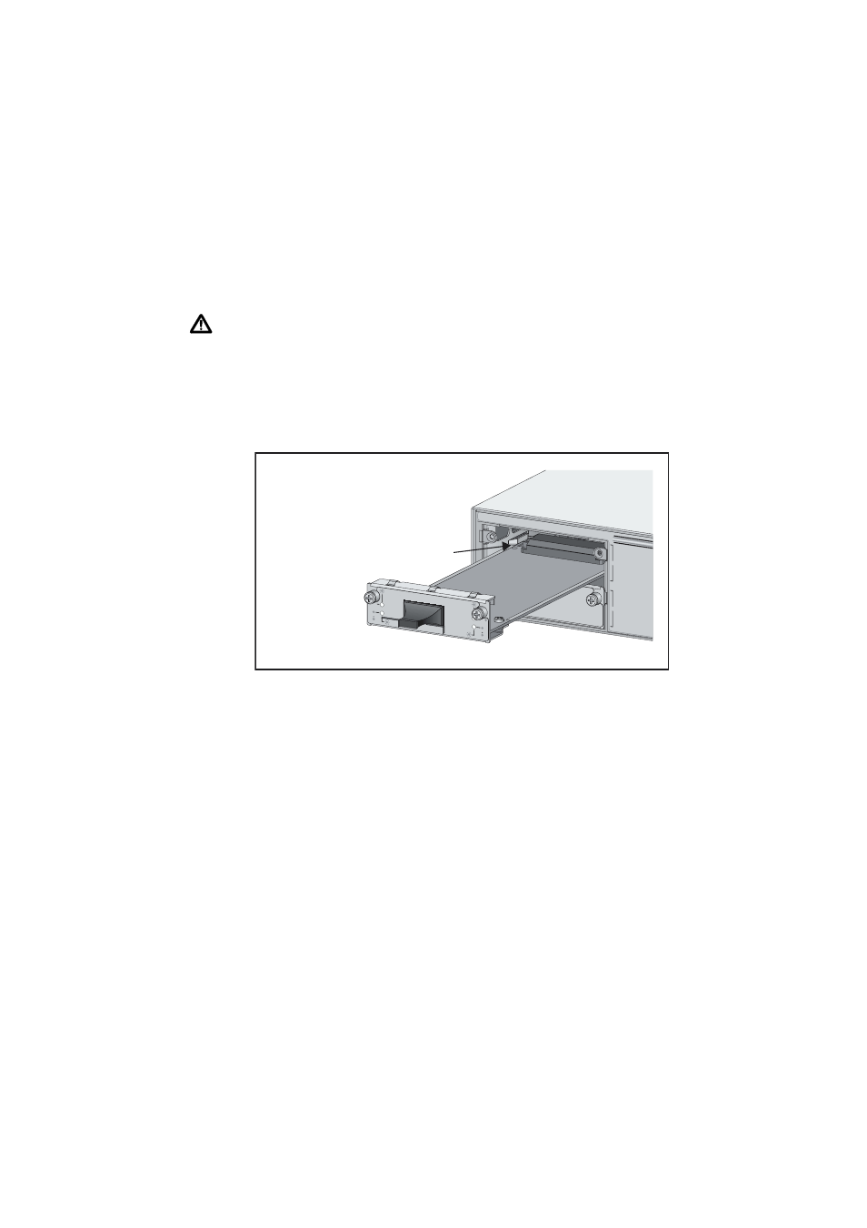
6. Slide the uplink module into place.
Make sure the module is aligned with the card guides on each side of the bay
(see the following figure).
7. Secure the uplink module to the switch.
Firmly press the uplink module until its connectors engage the uplink bay
connectors inside the switch.
Use a screwdriver to tighten the uplink module’s screws. Do not over-tighten
the screws.
8. For AT-A42/GBIC uplink modules, install the GBIC.
Slide the GBIC into the uplink’s GBIC slot. Press the GBIC firmly into place.
A range of GBICs have been tested and approved for use with AT-A42 uplink
modules. Contact your authorised Allied Telesis distributor or reseller for more
information, or visit
.
RX and TX terminal locations on SC fibre GBIC ports are the reverse of TX and
RX terminal locations on fixed SC fibre ports. When looking at an SC fibre
GBIC from the front, the RX terminal is on the left and the TX terminal is on
the right.
A
B
AT-A35/SX
1000BASE-FX/SC
RX
TX
LINK
ACTIVITY
FULL DUP
HALF DUP
COL
LINK
ACTIVITY
FULL DUP
HALF DUP
COL
COL
Card Guide