Allied Telesis Uplink Module User Manual
Page 4
4
Uplink Module
613-000689 Rev A
2. Gather the tools and equipment you will need.
A medium-sized flat-bladed screwdriver may be useful when loosening the uplink
module thumbscrews. You should also have any cables required for connecting
the uplink module to other network devices.
AT-A42/GBIC uplink modules require a GBIC before they can be connected to
a network.
3. Remove power to the switch or router.
Warning Do not install an uplink module into a switch without first removing
power from the switch. Be sure to disconnect both the main power supply and
any attached redundant power supply. Installing an uplink module with the switch
powered ON can damage the module and the switch.
The power cord and the redundant power supply cable are used to disconnect
AC switches. To de-energise the equipment, disconnect the power cord and the
redundant power supply cable.
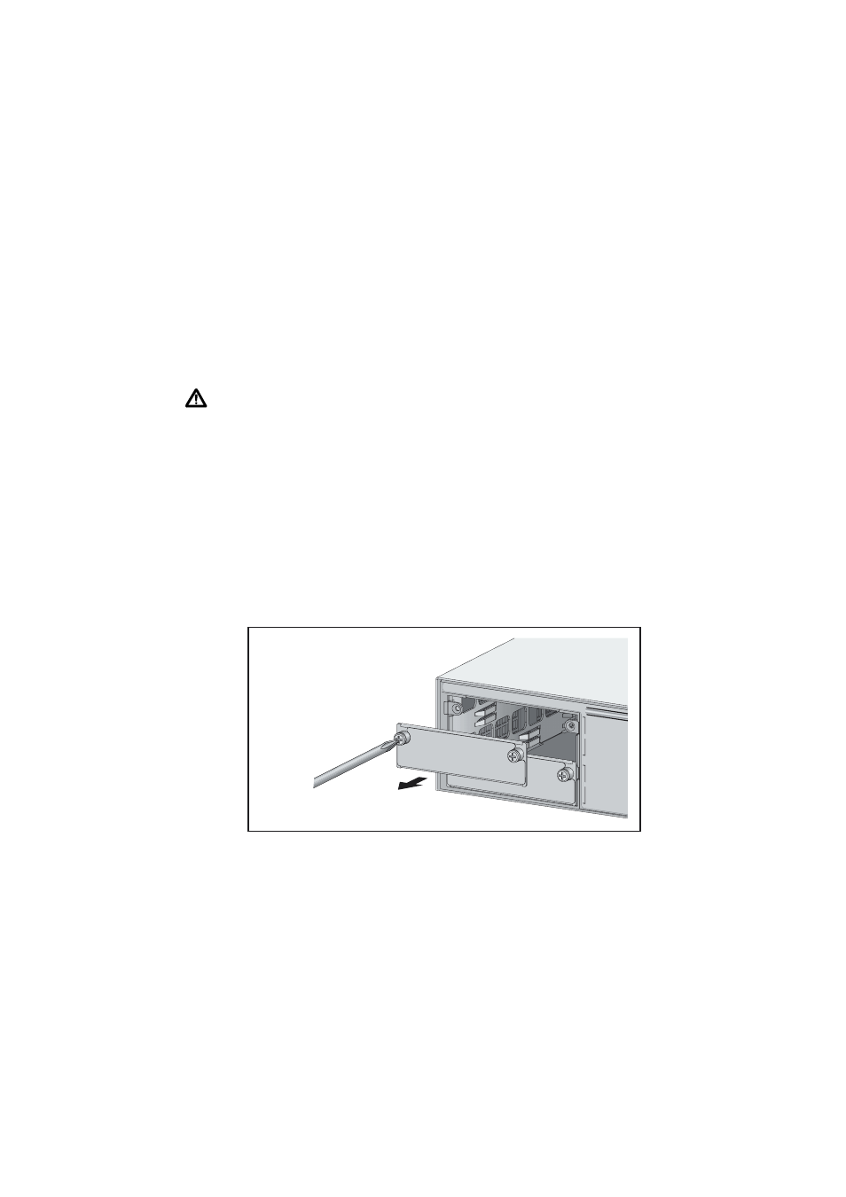
4. Remove the appropriate uplink bay face-plate on the switch’s front
panel.
Remove the appropriate face-plate as shown in the following figure. If your
switch has multiple uplink bays, and no uplink modules are currently installed,
then install the uplink module into the switch's top bay. This simplifies VLAN
configuration.
Keep the face-plate for future use. If you should remove the uplink module,
replace the face-plate to prevent dust and debris from entering the switch and to
maintain proper airflow.
A
B