Figure 28: cist and vlan guideline - example 2 – Allied Telesis AT-S63 User Manual
Page 248
Chapter 22: Multiple Spanning Tree Protocol
248
Section V: Spanning Tree Protocols
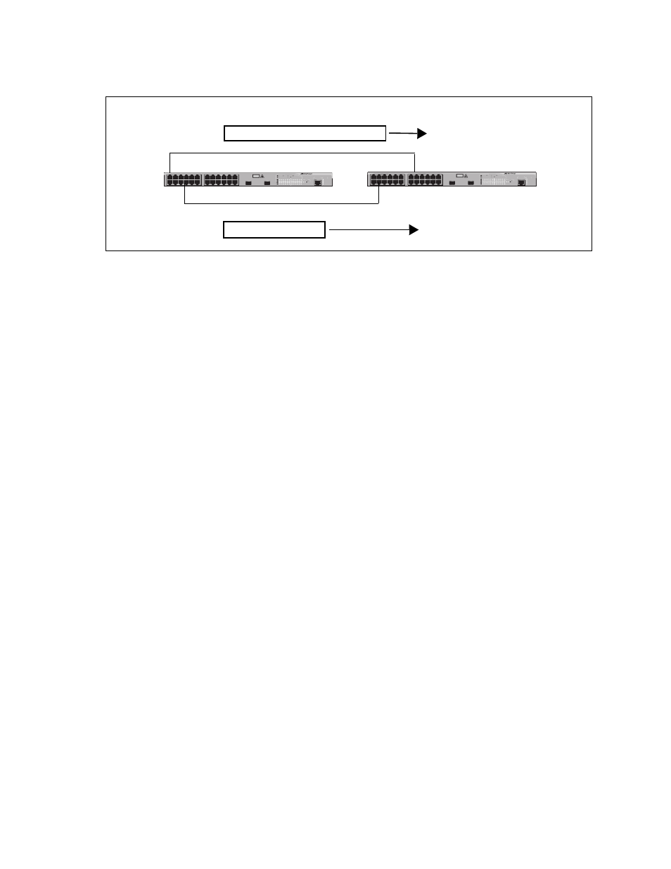
Figure 28. CIST and VLAN Guideline - Example 2
When port 4 on switch B receives a BPDU, the switch notes the port
sending the packet belongs only to CIST. Therefore, switch B uses CIST
in determining whether a loop exists. The result would be that the switch
detects a loop because the other port is also receiving BPDU packets from
CIST 0. Switch B would block a port to cancel the loop.
To avoid this issue, always assign all VLANs on a switch, including the
Default_VLAN, to an MSTI. This guarantees that all ports on the switch
have an MSTI ID and that helps to ensure that loop detection is based on
MSTI, not CIST.
FAULT
RPS
MASTER
POWER
CLASS 1
LASER PRODUCT
STATUS
TERMINAL
PORT
1
3
5
7
9
11
2
4
6
8
10
12
13
15
17
19
21
23R
14
16
18
20
22
24R
AT-9424T/SP
Gigabit Ethernet Switch
1
3
5
7
9
11
13
15
17
19
21
23R
2
4
6
8
10
12
14
16
18
20
22
24R
23
24
L/A
D/C
D/C
L/A
D/C
L/A
1000 LINK / ACT
HDX / COL
FDX
10/100 LINK / ACT
PORT ACTIVITY
L/A
1000 LINK / ACT
SFP
SFP
24
SFP
23
Switch A
Switch B
Port 1
Port 8
BPDU Packet
BPDU Packet
Instances: CIST 0 and MSTI 10
Instances: CIST 0
Port 15
Port 4