Connectors and port pinouts, Figure 21. rj-45 connector and port pin layout – Allied Telesis AT-FS750/48 User Manual
Page 55
AT-FS750/48 Fast Ethernet WebSmart Switch Installation Guide
55
Connectors and Port Pinouts
This section lists the connectors and connector pinouts for the
AT-FS750/48 Fast Ethernet WebSmart switch and its components.
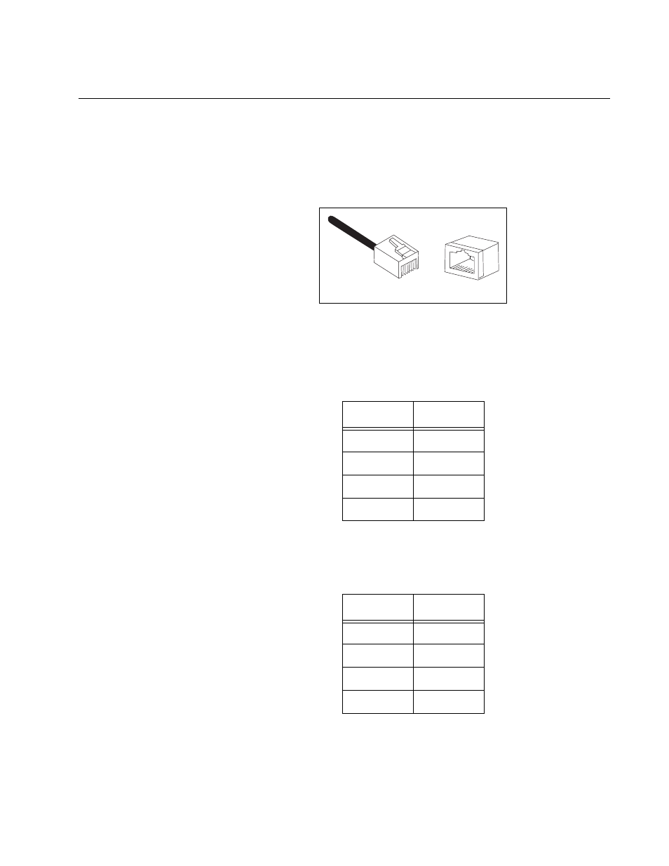
Figure 21 illustrates the pin layout for an RJ-45 connector and port.
Figure 21. RJ-45 Connector and Port Pin Layout
Table 8 lists the RJ-45 pin signals when a twisted pair port is operating in
the MDI configuration.
Table 9 lists the RJ-45 port pin signals when a twisted pair port is
operating in the MDI-X configuration.
Table 8. MDI Pin Signals (10Base-T or 100Base-TX)
Pin
Signal
1
TX+
2
TX-
3
RX+
6
RX-
Table 9. MDI-X Pin Signals (10Base-T or 100Base-TX)
Pin
Signal
1
RX+
2
RX-
3
TX+
6
TX-
8
8
1
1
See also other documents in the category Allied Telesis Computer hardware:
- AT-GS908M (54 pages)
- AT-x230-10GP (80 pages)
- AT-GS950/48PS (64 pages)
- AT-GS950/10PS (386 pages)
- AT-GS950/16PS (386 pages)
- AT-GS950/48PS (386 pages)
- AT-9000 Series (258 pages)
- AT-9000 Series (1480 pages)
- IE200 Series (70 pages)
- AT-GS950/8 (52 pages)
- AT-GS950/48 (378 pages)
- AT-GS950/48 (60 pages)
- AT-GS950/48 (410 pages)
- SwitchBlade x8106 (322 pages)
- SwitchBlade x8112 (322 pages)
- SwitchBlade x8106 (240 pages)
- SwitchBlade x8112 (240 pages)
- AT-TQ Series (172 pages)
- AlliedWare Plus Operating System Version 5.4.4C (x310-26FT,x310-26FP,x310-50FT,x310-50FP) (2220 pages)
- FS970M Series (106 pages)
- 8100S Series (140 pages)
- 8100L Series (116 pages)
- x310 Series (116 pages)
- x310 Series (120 pages)
- AT-GS950/24 (366 pages)
- AT-GS950/16 (44 pages)
- AT-GS950/24 (404 pages)
- AT-GS950/16 (404 pages)
- AT-GS950/16 (364 pages)
- AT-GS950/8 (404 pages)
- AT-GS950/8 (364 pages)
- AT-GS950/8 (52 pages)
- AT-8100 Series (330 pages)
- AT-8100 Series (1962 pages)
- AT-FS970M Series (1938 pages)
- AT-FS970M Series (330 pages)
- SwitchBlade x3106 (288 pages)
- SwitchBlade x3112 (294 pages)
- SwitchBlade x3106 (260 pages)
- SwitchBlade x3112 (222 pages)
- AT-S95 CLI (AT-8000GS Series) (397 pages)
- AT-S94 CLI (AT-8000S Series) (402 pages)
- AT-IMC1000T/SFP (23 pages)
- AT-IMC1000TP/SFP (24 pages)
- AT-SBx3106WMB (44 pages)