Wall-mounting the switch, Figure 4. wall mounting hole dimensions – Allied Telesis AT-FS705L User Manual
Page 28
Chapter 2: Installation
28
Wall-Mounting the Switch
You can mount the switch vertically on a wall using the mounting brackets
that come with the unit. The wall-mounting screws and plastic anchors
necessary to mount the switch on a wall are provided.
Note
The plastic anchors used for wall mounting the switch are intended
for installation in walls made of sheetrock or concrete materials.
To mount an AT-FS705L switch onto a wall, perform the following
procedure:
1. Remove all equipment from the package and store the packaging
material in a safe place.
2. If attached, remove the rubber feet, data cables, and power cord from
the switch.
3. Select a wall location for the switch.
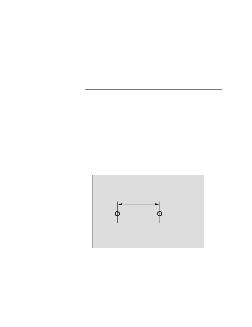
4. Mark locations for two holes 7.06 cm (2.78 in) apart on the wall as
shown in Figure 4..
Figure 4. Wall Mounting Hole Dimensions
5. At the marked locations for the holes, drill the holes for the
anchors.Each hole must be 0.635 mm (0.25 in) in diameter.
6. Install the two anchors and then the two screws.
7.06cm (2.78in)
1781