Configuration diagrams, continued – ADIC Scalar 1000 User Manual
Page 15
Configuration Diagrams
thirteen
Configuration Diagrams,
continued
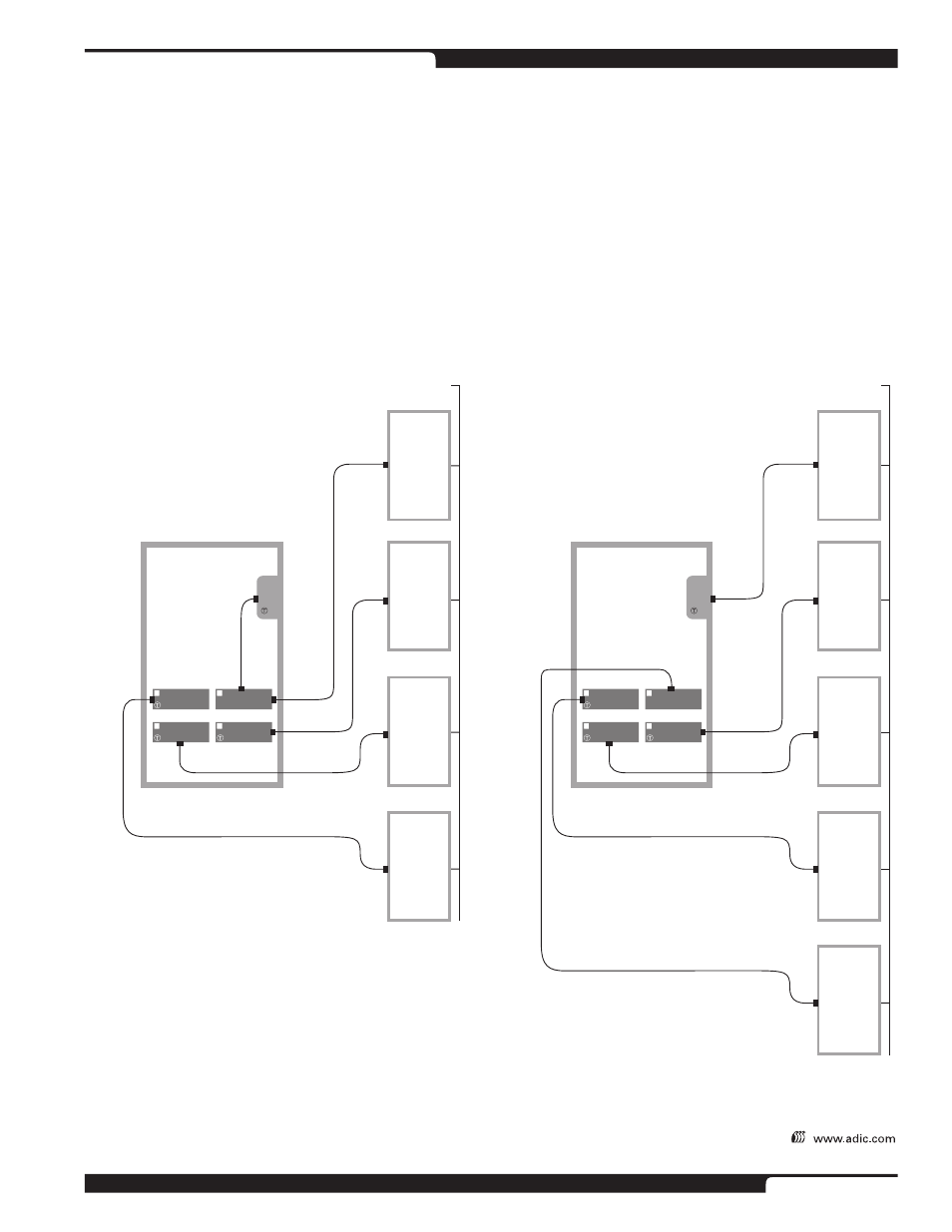
The following two examples illustrate different ways to configure a Scalar 1000 within a multihost environment.
The AMU, consisting of a control computer and DAS software, allows customers to connect multiple servers to
the same Scalar 1000 library at the same time. Specifically, the AMU’s functions include:
• Provides host communication
• User interface for operation and service
• Robotic controller communication
• Tape slot management
The diagram below depicts a typical Scalar 1000 with IBM 3590 drives, running an AMU configuration.
6' Controller–to–drive cable
Drive 3
Drive 4
Drive 2
Drive 1
Robotic
Controller
15' or 30' cable
Scalar 1000
Control Module with
4 drives and
multihost–aware
backup software
Backup
Server 3
Backup
Server 4
Backup
Server 2
15' or 30' cable
Network
Backup
Server 1
15' or 30' cable
15' or 30' cable
Scalar Scenario—Multi–Host
(SCSI) Environment
Software Controlled
“Servers 2, 3 and 4 send robotic
requests to Server 1.”
Drive 4
Drive 3
Drive 2
Drive 1
Robotic
Controller
15' or 30' cable
Scalar 1000
Control Module with 4 IBM 3590
drives and multihost–capable
hardware (AMU)
Backup
Server 2
Backup
Server 3
Backup
Server 1
15' or 30' cable
Network
AMU
15' or 30' cable
15' or 30' cable
Scalar Scenario—Multi–Host
(SCSI) Environment
Hardware Controlled
“Servers 1, 2, 3 and 4 send
robotic requests to the AMU.”
Backup
Server 4
15' or 30' cable