Signalon, Series – ADC RF Signal Management SignalOn Series User Manual
Page 11
5/08
•
102721AE
SignalOn
®
Series
11
w w w . a d c . c o m
•
+ 1 - 9 5 2 - 9 3 8 - 8 0 8 0
•
1 - 8 0 0 - 3 6 6 - 3 8 9 1
SignalOn
®
Series
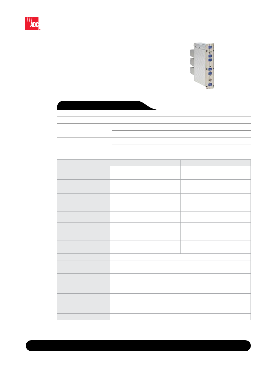
Actives: Forward Path Amplifier
Actives: Amplifier Modules
Amplifier
(front view)
PeRFoRMANCe ATTRiBUTe
20 dB Forward Amplifier
30 dB Forward Amplifier
Bandwidth
50-1000 MHz
50-1000 MHz
optimum RF input
+20 dBmV per channel
+10 dBmV per channel
Minimum full gain
20.0 dB
30.0 dB
Gain adjustment range
10 +/-1 dB in 0.5 dB steps
10 +/-1 dB in 0.5 dB steps
Tilt adjustment range
10 +/-1 dB @ 50 MHz in 0.5 dB steps
10 +/-1 dB @ 50 MHz in 0.5 dB steps
Gain flatness
+/- 0.4 dB from 50 to 870 MHz
+/- 0.5 dB from 870 to 1000 MHz
+/- 0.45 dB from 50 to 870 MHz
+/- 0.65 dB from 870 to 1000 MHz
Return loss,
input and output ports
-19.0 dB from 50 to 870 MHz
-16.5 dB from 870 to 1000 MHz
-18.0 dB from 50 to 870 MHz
-15.0 dB from 870 to 1000 MHz
Noise figure
7.3 dB from 50 to 870 MHz
7.6 dB from 870 to 1000 MHz
5.7 dB from 50 to 870 MHz
6.2 dB from 870 to 1000 MHz
CTB1
-73.1 dB
-78.9 dB
CSo1
-81.7 dB
-84.5 dB
iMD1
-78.2 dB
-83.7 dB
Monitor ports
-20 dB test point for both RF input and RF output
Power dissipation
17W max
operating temperature
0 - 50 degrees C
Dimensions
8.55"H x 1.67"W x 7.81"D
Power connector
gold-on-gold, slide-on contacts
Thermal shock
Meets MIL-STD-202 Method 107
office vibration
Meets GR-63-Core Section 5.4.2
Mechanical shock
Meets MIL-STD-202 Method 213
Accelerated aging
Meets MIL-STD-202 Method 108
NeBS
Meets NEBS Level 3
O r d e r i n g I n f o r m a t i o n
Description
Catalog Number
Forward Path Amplifier Modules
BNC connector
20 dB
N-MAB20FA
30 dB
N-MAB30FA
F connector
20 dB
N-MAF20FA
30 dB
N-MAF30FA
Note: Measured with 110 channel loading and optimum RF input level at full gain and no tilt. Specifications are typical
worst-case numbers across the given frequency range, unless otherwise noted, and are subject to change without notice.