Figure 4. at-2973t faceplate, L/a 1 l/a 2 – Allied Telesis NETEXTREME II AT-2973SX User Manual
Page 19
AT-2973SX, AT-2973T, and AT-2973T/4 NetExtreme II Family Adapters Installation and User’s Guide
19
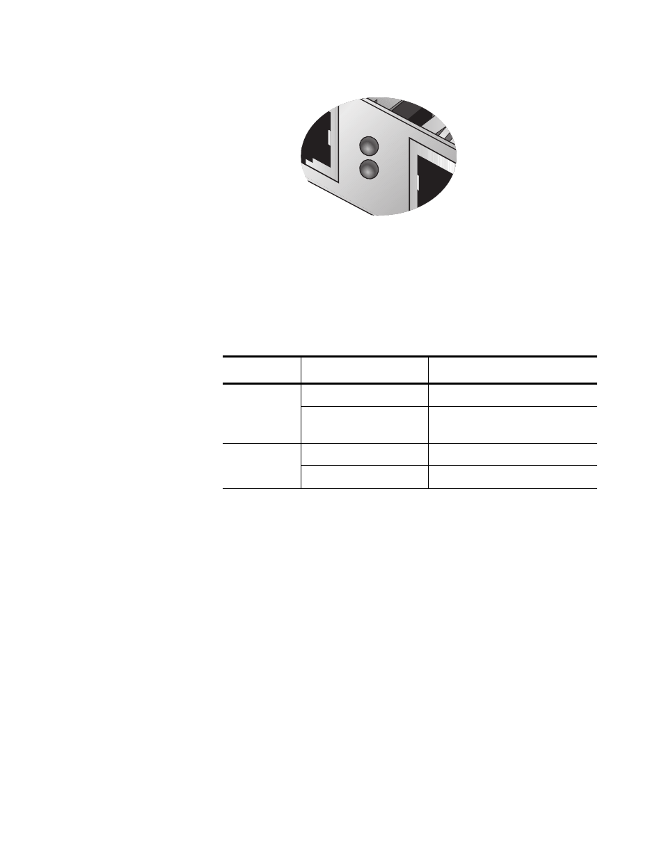
Figure 4. AT-2973T Faceplate
For copper-wire Ethernet connections, the state of the network link and
activity is indicated by the LEDs on the RJ-45 connector. The LED labeled
L/A1 indicates port 1 and the LED labeled L/A2 indicates port 2. See
Table 2.
Table 2. Network Link and Activity Indicated by the RJ-45 Port LEDs
Port LED
LED Appearance
Network State
Link LED
Off
No link (cable disconnected)
Continuously
illuminated
Link
Activity LED
Off
No network activity
Blinking
No network activity
1701
100
L/A
1
L/A
2
This manual is related to the following products: