Ov2. theory of operation, Ov2.1 optical system – Campbell Scientific TGA100A Overview User Manual
Page 3
TGA100A Trace Gas Analyzer Overview
OV2. Theory of Operation
OV2.1 Optical System
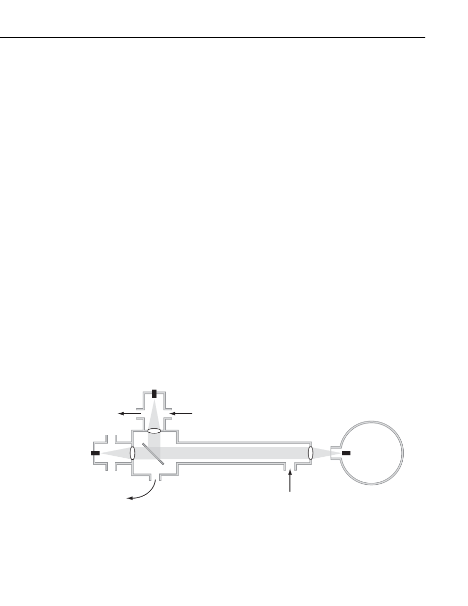
The TGA100A optical system is shown schematically in Figure OV2.1-1. The
optical source is a lead-salt tunable diode laser that operates between 80 and
140 K, depending on the individual laser. Two options are available to mount
and cool the laser: the TGA100A LN2 Laser Dewar and the TGA100A Laser
Cryocooler System. Both options include a laser mount that can accommodate
one or two lasers (up to four lasers can be installed by adding the optional
second laser mount). The LN2 Laser Dewar mounts inside the analyzer
enclosure. It holds 10.4 liters of liquid nitrogen, and must be refilled twice per
week. The Laser Cryocooler System uses a closed-cycle refrigeration system to
cool the laser without liquid nitrogen. It includes a vacuum housing mounted
inside the analyzer enclosure, an AC-powered compressor mounted outside the
enclosure, and 3.1 m (10 ft) flexible gas transfer lines.
The laser is simultaneously temperature and current controlled to produce a
linear wavelength scan centered on a selected absorption line of the trace gas.
The IR radiation from the laser is collimated and passed through a 1.5 m
sample cell, where it is absorbed proportional to the concentration of the target
gas. A beam splitter directs most of the energy through a focusing lens and
short sample cell to the sample detector, and reflects a portion of the beam
through a second focusing lens and a short reference cell to the reference
detector. A prepared reference gas having a known concentration of the target
gas flows through the reference cell. The reference signal provides a template
for the spectral shape of the absorption line, allowing the concentration to be
derived independent of the temperature or pressure of the sample gas or the
spectral positions of the scan samples. The reference signal also provides
feedback for a digital control algorithm to maintain the center of the spectral
scan at the center of the absorption line. The simple optical design avoids the
alignment problems associated with multiple-path absorption cells. The
number of reflective surfaces is minimized to reduce errors caused by Fabry-
Perot interference.
Reference
Detector
Laser
Sample In
Reference Gas In
To Pump
Sample Cell
Sample
Detector
To Pump
Dewar
FIGURE OV2.1-1. Schematic Diagram of TGA100A Optical System
OV-3