Ov1. system components – Campbell Scientific TGA100A Overview User Manual
Page 2
TGA100A Trace Gas Analyzer Overview
OV1. System Components
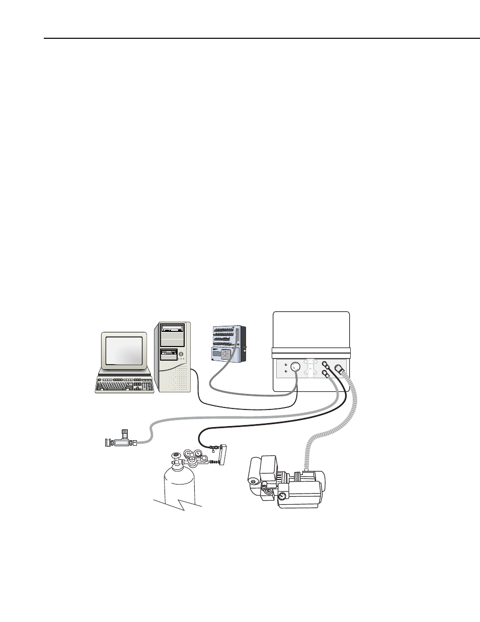
Figure OV1-1 illustrates the main system components needed to operate the
TGA100A. These system components include:
•
TGA100A Analyzer: The analyzer optics and electronics, mounted in an
insulated fiberglass enclosure.
•
Computer: A user-supplied computer to display data and set parameters.
•
Optional Datalogger (CR5000 shown): Receives concentration data from
the TGA100A through the SDM interface cable.
•
Sample Intake (15838 shown): Filters the air sample and sets its flow rate.
•
Sample pump (RB0021-L shown): Pulls the air sample and reference gas
through the analyzer at low pressure.
•
Suction hose (7123 shown): Connects the analyzer to the sample pump.
Supplied with RB0021 sample pump.
•
Reference gas: tank of reference gas, with pressure regulator (supplied by
user).
•
Reference gas connection (15837 shown): Flow meter, needle valve, and
tubing to connect the reference gas to the analyzer.
CAUTION
DC ONLY
SN:
Logan, Utah
MADE IN USA
CR5000 MICROLOGGER
H
L
1
DIFF
1
2
H
L
2
3
4
H
L
3
5
6
H
L
4
7
8
H
L
5
9 10
H
L
6
11 12
H
L
7
13 14
H
L
8
15 16
H
L
9
17 18
H
L
10
CS I/O
(OPTICALLY ISOLATED)
RS-232
COMPUTER
19 20
SE
H
L
11
DIFF
21 22
H
L
12
23 24
H
L
13
25 26
H
L
14
27 28
H
L
15
29 30
H
L
16
31 32
H
L
17
33 34
H
L
18
35 36
CONTROL I/O
CONTROL I/O
POWER
UP
GROUND
LUG
pc card
status
G
G 12V
12V
Hm
A B C
D E F
J K L
G H I
M N O
T U V
P R S
W X Y
* / )
- + (
< = >
Spc Cap
$ Q Z
, ' _
1
2
PgUp
ENTER
BKSPC
SHIFT
ESC
PgDn
End
Del
Ins
Graph/
char
3
4
5
6
7
8
9
0
CURSOR
ALPHA
POWER IN
11 - 16 VDC
H
L
19
37 38
H
L
20
39 40
SE
VX1
VX2
VX3
VX4
CAO1
CAO2
IX1
IX2
IX3
IX4
IXR
P1
P1
C1
C2
C3
C4
G
C6
C5
C7
C8
G
G
>2.0V
<0.8V
5V
5V
G
SDI-12
12V
G
SDM-C2
SDM-C3
SDM-C1
G
12V
G
SW-12
SW-12
G
POWER OUT
TGA100A Analyzer
Datalogger
Computer
SDM Cable
Ethernet Cable
Suction Hose
Sample Pump
Sample Intake
Reference Gas Connection
Reference Gas
FIGURE OV1-1. TGA100A System Components
OV-2