Datalogger programming – Campbell Scientific TB4 and TB4MM Hydrological Services Rain Gage User Manual
Page 9
TB4 and TB4MM Rain Gage
Dataloggers listed in Table 4-2 have the capability of counting switch closures
on some of their control ports. When a control port is used, the return from the
rain gage switch must be connected to +5 volts on the datalogger.
TABLE 4-2. Wiring for Control Port Input
Color
Description
CR800
CR1000
CR3000
CR500
CR510
CR10X
CR23X
Black
Signal
Control Port C2/P3
Control Port Control Port
White Signal Return 5 V
5 V
5 V
5 V
Clear Shield
G
The CR10 does not support the use of control port inputs with the Pulse Count
instruction.
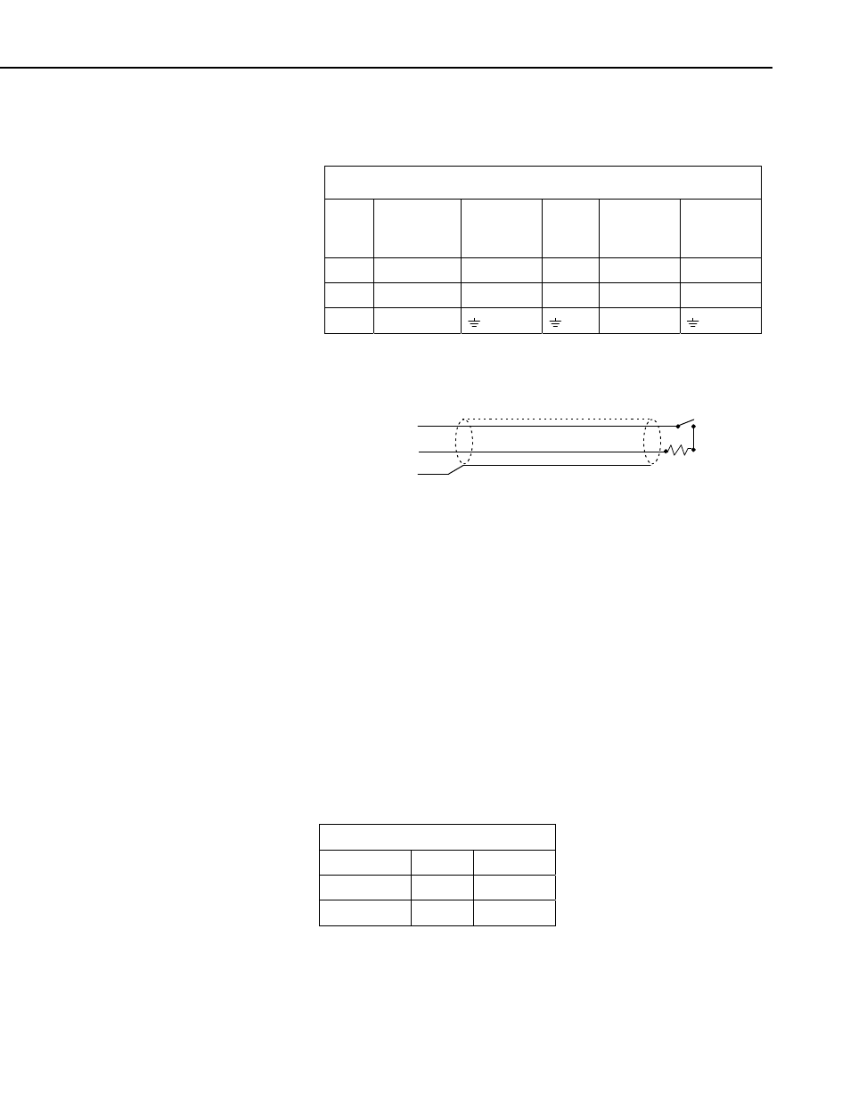
Black
White
Clear
100
Ω
FIGURE 4-1. Rain Gage Schematic
In a long cable there is appreciable capacitance between the lines. A built up
charge could cause arcing when the switch closes, shortening switch life. A
100 ohm resistor is connected in series at the switch to prevent arcing by
limiting the current (Figure 4-1). This resistor is installed on all rain gages
currently sold by Campbell Scientific.
5. Datalogger Programming
This section is for users who write their own datalogger programs. A
datalogger program to measure this sensor can be created using Campbell
Scientific’s Short Cut Program Builder software. You do not need to read this
section to use Short Cut.
The rain gage is measured using the Pulse Count instruction with the switch
closure configuration code. The multiplier used in the Pulse Count instruction
determines the units in which rainfall is reported.
TABLE 5-1. Multipliers
TB4
TB4MM
Inches
0.01 0.007874
Millimeters
0.254 0.2
5