4 slowsequence instruction, Using the rs232 serial diagnostics port, 1 connecting to the rs232 user port – Campbell Scientific SDM-CAN Datalogger to CANbus Interface User Manual
Page 48: Slowsequence instruction, Connecting to the rs232 user port, 1. rs232
SDM-CAN Datalogger-to-CANbus Interface
'\\\\\\\\\\\\\\\\\\ ALIASES & OTHER VARIABLES //////////////////
Alias CANBlk1(1) = Accel_Pedal 'Assign an alias name to CANBlk1(1)
'\\\\\\\\\\\\\\\\\\\\\\\\\\\ PROGRAM ///////////////////////////
BeginProg 'Program begins here
'MainSequence
Scan(PERIOD,P_UNITS,0,0) 'Scan once every 1 Secs, non-burst
'__________________________ CAN Blocks __________________________
'Read status of digital I/O port, return value to NewData variable
ReadIO(NewData,7,&B1)
'When digital I/O port is high retrieve data from CAN network
If NewData > 0 Then
CanBus(CANBlk1(),ADDRESS1,TQUANTA,TSEG1,TSEG2, 217056000,
DATATYPE1,STARTBIT1,NUMBITS1,NUMVALS1,1,0)
EndIf
Next Scan 'Loop up for the next scan
EndProg 'Program ends here
Due to current system constraints the ID parameter must be
entered directly into the CanBus instruction.
NOTE
4.2.4 SlowSequence Instruction
It is also possible to have a SlowSequence Scan for low priority CANbus
measurements that are not needed at the rate of the primary scan interval. The
CR9000 or CR5000 tags on measurement instructions from the slow sequence
scan to the normal scan as time allows.
Please refer to the CR9000 or CR5000 on-line help for a more detailed
explanation of the SlowSequence instruction.
5. Using the RS232 Serial Diagnostics Port
5.1 Connecting to the RS232 User Port
The user communication port is a DCE configured, 9 pin RS232 port. The port
automatically powers up when it detects valid RS232 signals and shuts down
after a period of inactivity. The SDM-CAN automatically detects the incoming
baud rates in the range from 1200 to 115200 baud. It is configured to work
with eight data bits, one start bit and stop bit and no parity. The pin out of the
RS232 DCE 9 pin ‘D’ plug is shown in TABLE 5-1.
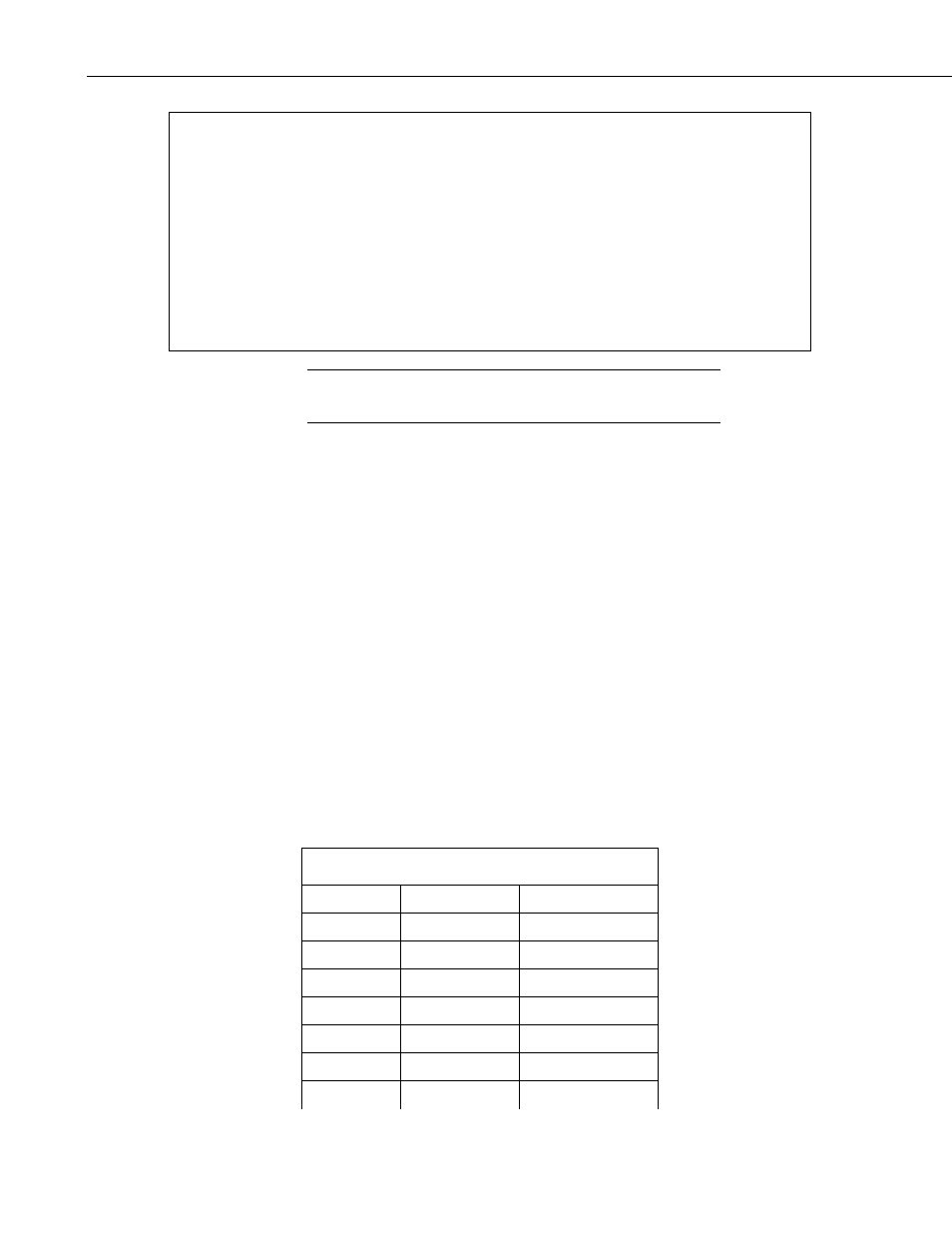
TABLE 5-1. RS232 Pin Out
Pin Number RS232 function Direction of signal
1 DCD input.
2 RX input.
3 TX Output.
4 DTR Output.
5 0V Ground.
6 DSR input.
7 RTS Output.
40