3 troubleshooting, 3 solar radiation, 1 general description – Campbell Scientific RAWS-P Remote Automated Weather Station User Manual
Page 16: 2 wiring, Troubleshooting, Solar radiation, General description, Wiring, 3. solar rad sdi-12 connector (color coded green)
RAWS-P Remote Automated Weather Station
4.2.3 Troubleshooting
If a problem is suspected, check the sensor cable. Disconnect the connector
and use a digital volt meter (DVM) to check the resistance between Pin A
(sensor signal) and Pin C (sensor ground). The resistance should read as an
open circuit until you move the rain gage tipping mechanism where the magnet
swings past the reed relay. Try connecting a substitute sensor. Obtain an
RMA number before returning this sensor to Campbell Scientific for repair.
Consult the TE525-L manual for more information.
NOTE
4.3 Solar Radiation
4.3.1 General Description
The Apogee Pyranometer (pn CS300-LQ) measures incoming solar radiation
with a silicon photovoltaic detector mounted in a cosine-corrected head. The
detector outputs current; a shunt resistor in the sensor converts the signal from
current to voltage. During the night, the CS300-LQ may read slightly negative
incoming solar radiation. The negative signal is caused by RF noise.
4.3.2 Wiring
The CS300-LQ attaches to the connector labeled SOLAR RAD SDI-12; this
connector is color coded green. The pyranometer sensor is internally wired
from the RAWS connector panel to the CR1000 datalogger.
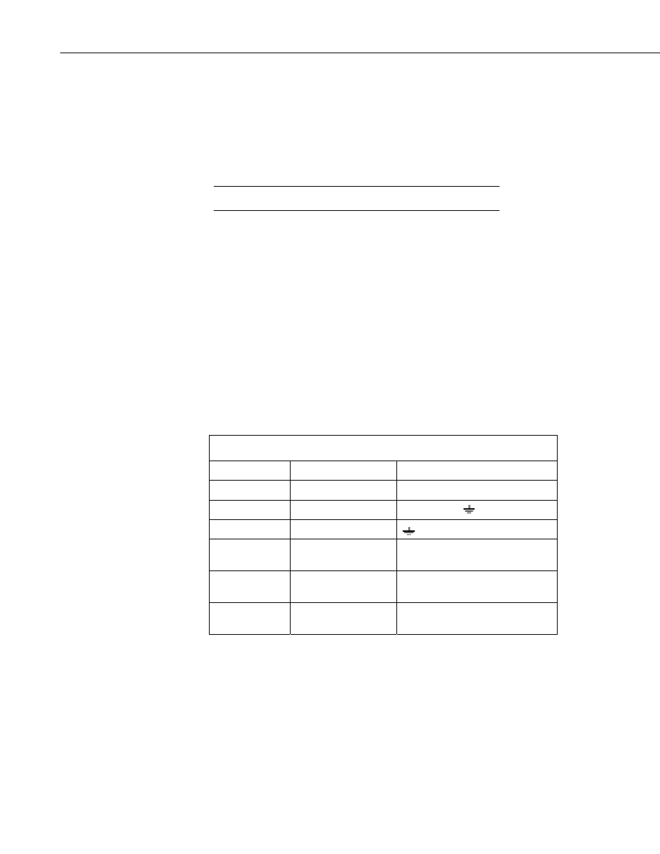
TABLE 4-3. SOLAR RAD SDI-12 Connector (color coded green)
Connector Pin
Description
CR1000 Terminal
A
Solar Sensor +
3H
B
Solar Sensor -
3L shorted to
C
Solar Sensor Ground
D
SDI-12 Ground
G (used for a second SDI-12
sensor)
E
SDI-12 Signal
C5 (used for a second SDI-12
sensor)
F
SDI-12 12 V
12V (used for a second SDI-12
sensor)
4.3.3 Troubleshooting
If a problem is suspected, check the sensor cable. Disconnect the connector
and use a DVM to check the voltage between Pin A Solar Sensor (+) and Pin B
Solar Sensor (-). The voltage should be 0 to 200 mV for 0 to 1000 W m
-2
radiation. No voltage indicates a problem with either the photodiode or the
shunt resistor, both of which are potted in the sensor head and cannot be
serviced. Try connecting a substitute sensor. Obtain an RMA number before
returning this sensor to Campbell Scientific for repair.
8