Initial inspection, Quickstart, 1 physical setup – Campbell Scientific NL115 Ethernet Interface and CompactFlash Module User Manual
Page 8: Physical setup, 1. nl115 attached to a cr1000
NL115 Ethernet and CompactFlash
®
Module
•
An NL115 with a serial number less than 10297 requires a firmware
update to function properly when attached to a CR3000 datalogger with a
serial number greater than 6260. This update must be performed by
Campbell Scientific. If you require this firmware update, see the
section at the front of this manual for information on returning
your NL115 to Campbell Scientific.
3. Initial Inspection
Upon receipt of the NL115, inspect the packaging and contents for damage.
File damage claims with the shipping company.
4. Quickstart
This section describes the basics of communicating via Ethernet and storing
and retrieving datalogger data. These operations are discussed in detail in
Section 7, Operation.
4.1 Physical Setup
Always power down the datalogger before installing to or
removing the NL115 from the datalogger.
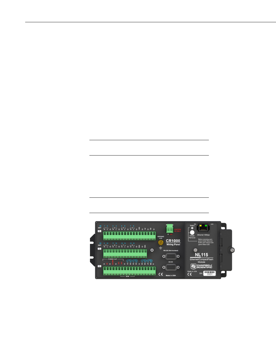
After powering down the datalogger, plug the NL115 into the datalogger
peripheral port (see FIGURE 4-1). Attach Ethernet cable to the 10Base-T port.
If using the 28033 surge protector, connect the other end of the Ethernet cable
to the 28033 and connect another Ethernet cable to the other end of the 28033.
Restore power to the datalogger. Insert formatted CF card. (For instructions
on formatting a CF card, see Appendix A, CF Card Maintenance.)
A CF card does not need to be present in order to use the NL115’s
TCP/IP functionality.
FIGURE 4-1. NL115 attached to a CR1000
CAUTION
NOTE
2