3 wiring to the datalogger, Wiring to the datalogger, 1. cs300 schematic – Campbell Scientific CS300 Silicon Pyranometer User Manual
Page 17
CS300 Pyranometer
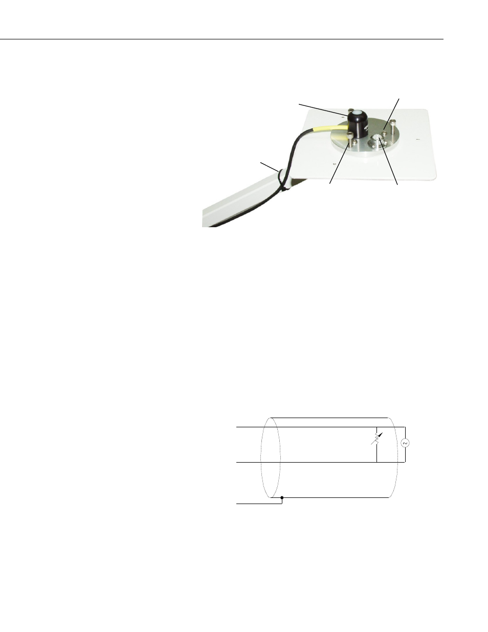
3. Loosely mount the 18356 base/leveling fixture on the 015ARM. Do not
fully tighten the three mounting screws.
4. Turn the leveling screws as required to bring the bubble of the bubble level
within the ring.
5. Tighten the mounting screws to secure the assembly in its final position.
Check that the pyranometer is still correctly leveled and adjust as
necessary.
6. Route the sensor cable along the underside of the 015ARM’s arm to the
tripod/tower, and to the instrument enclosure.
7. Secure the cable to the mounting arm and mast using cable ties.
8. Remove the green cap after installing the sensor. Save this cap for
shipping or storing the sensor.
7.3 Wiring to the Datalogger
A schematic diagram of the CS300 is shown in FIGURE 7-1.
RED
BLACK
CLEAR
500 to 600 Ω
typical
Single-Ended
Analog Input
Ground/AG
Ground/G
FIGURE 7-1. CS300 schematic
Connections to Campbell Scientific dataloggers are given in TABLE 7-1.
When Short Cut is used to create the datalogger program, the sensor should be
wired to the channels shown in the wiring diagram created by Short Cut.
Cable Tie
CS300 Pyranometer
Mounting Screw
Leveling Screw
Bubble Level
9