Camera hardware description, 1 terminal block connections – Campbell Scientific CC640 Digital Camera User Manual
Page 11
CC640 Digital Camera
• Use the Device Configuration Utility to change settings in the camera and
other PakBus devices. Datalogger parameters can also be incorporated
into the datalogger program or changed with a keyboard display.
• Verify that the lens cable is properly seated, as the connector may
inadvertently become unplugged during handling or installation.
Device Configuration Utility is included in LoggerNet, PC400,
and as a free download.
NOTE
Always place the Power Switch in the Auto Position.
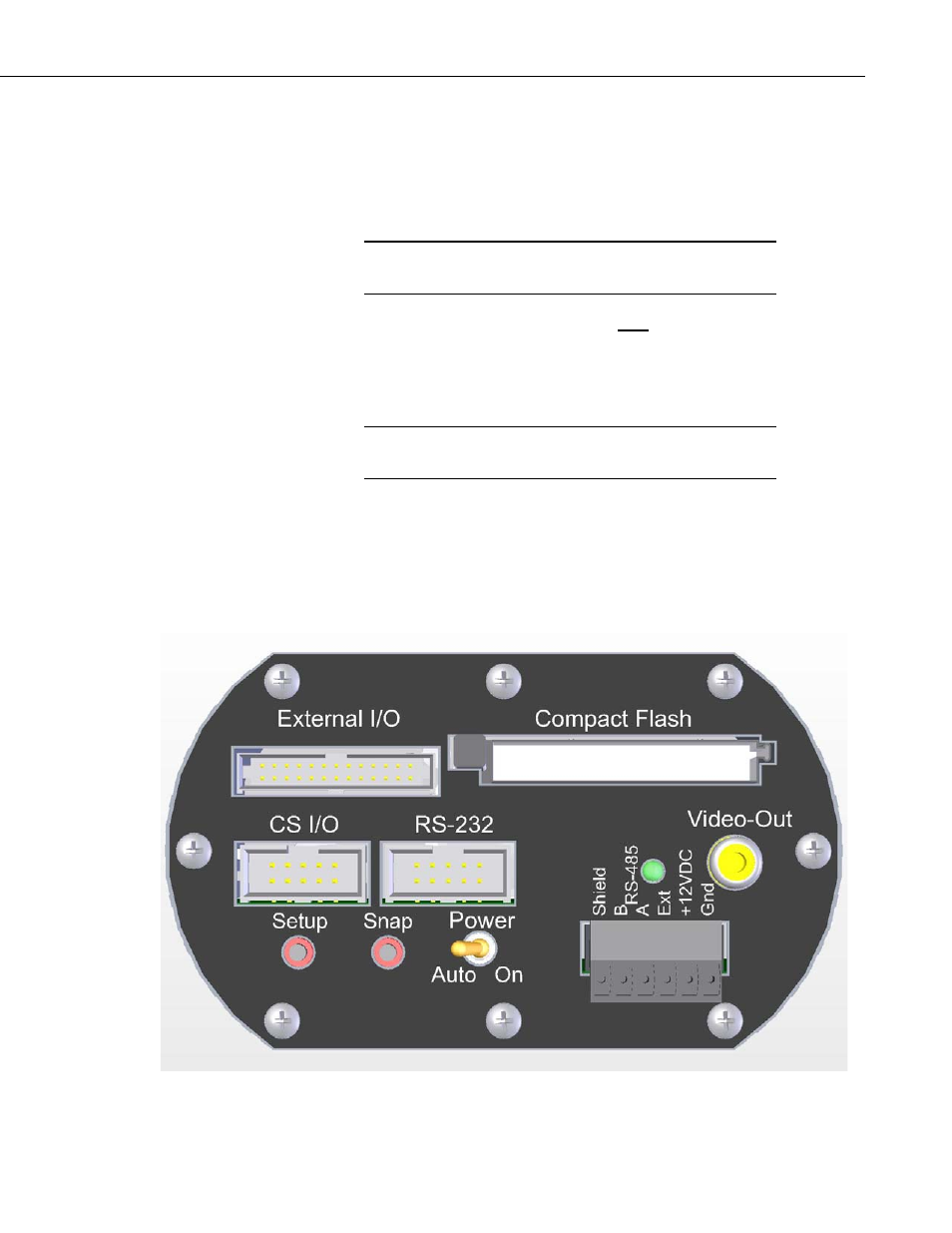
3. Camera Hardware Description
3.1 Terminal Block Connections
Only shielded cable should be used for connections to the
terminal block.
NOTE
Gnd Power
Ground
+12VDC
9-15VDC Power, 250 mA
Ext.
External Trigger Input, 5.0 Volt Logic Signal, 15Volts Max
RS-485A RS-485
communication
RS-485B RS-485
communication
Shield
The shield (drain wire) needs to be connected to this terminal
FIGURE 2. Terminal Block Position and Layout
5