2 potentiometer measurement, 3 four wire half bridge with measured excitation – Campbell Scientific AM416 Multiplexer User Manual
Page 18
AM416 RELAY MULTIPLEXER
12
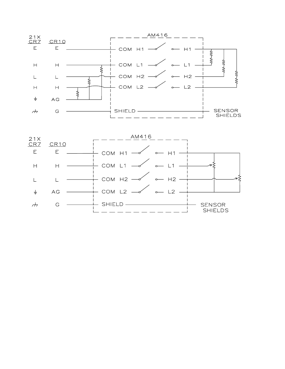
FIGURE 10. Half Bridge (Modified 107 Temperature Probe) Hook-up and Measurement.
FIGURE 11. Potentiometer Hook-up and Measurement
6.3.2 POTENTIOMETER MEASUREMENT
Sensor to Multiplexer wiring - up to two
potentiometers may be connected to one input
SET. Excitation and ground leads may be
common; signal leads must be routed
separately (Figure 11).
Multiplexer to Datalogger wiring - Signal lines
from two COM terminals are connected to two
consecutive single-ended analog input
channels. One COM terminal is connected to a
datalogger switched excitation channel, and the
remaining COM line connects to datalogger
ground. Up to 32 potentiometers may be
measured by two single-ended datalogger
channels.
6.3.3 FOUR WIRE HALF BRIDGE WITH
MEASURED EXCITATION
Sensor to Multiplexer Wiring - one sensor per
input SET.
Multiplexer to Datalogger Wiring - One COM
line is tied to a datalogger excitation channel,
and two COM lines to a differential analog input.
The remaining COM line is connected to the
high side of a differential channel along with a
fixed resistor. The other side of the resistor
connects to the low side of the channel, then
ground (Figure 12). Up to 16 four wire half-
bridges may be measured by two differential
datalogger channels in this manner.