2 the measurement terminals, 1 the com terminals, 2 the sensor input terminals – Campbell Scientific AM416 Multiplexer User Manual
Page 12: Datalogger programming, 1 single loop instruction sequence
AM416 RELAY MULTIPLEXER
6
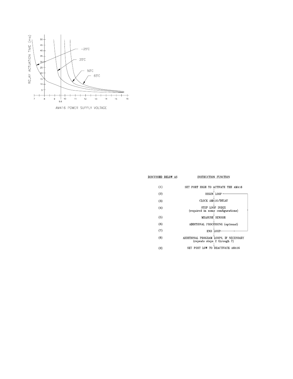
FIGURE 4. Actuation Time of Relays vs.
Temperature (oC) and Battery Voltage.
4.2 THE MEASUREMENT TERMINALS
The terminals that run the length of the AM416
are dedicated to the connection of sensors to
the datalogger (Figure 1). The 16 groups of 4-
terminal inputs allow attachment of stripped and
tinned sensor leads. The terminals marked
COM allow attachment of the common signal
leads that carry the sensor's signal between
multiplexer and datalogger. The shield lines
allow sensor shields to be routed through the
multiplexer and back to datalogger ground.
4.2.1 THE COM TERMINALS
The multiplexer terminals dedicated to
multiplexer-datalogger signal transfer are
located within the silk screened brackets
labeled COM (common; see Figure 1). The
four individual COM lines are labeled: H1
(common high #1), L1 (common low #1), H2
(common high #2), and L2 (common low #2).
The circuitry of each COM line is isolated from
the other three.
A shield terminal is also located within each
COM bracket. All shield terminals are in
electrical continuity at all times (i.e. they are not
switched). Their function is to provide a path to
ground for sensor cable shields. The shield
terminals within the COM bracket should be tied
to datalogger earth ground either directly or
through a busbar.
4.2.2 THE SENSOR INPUT TERMINALS
The input terminals for sensor attachment run
the length of the multiplexer and are subdivided
into 16 labeled groups. Each group consists of
four Simultaneously Enabled Terminals (SET).
Within each SET, the four terminals are labeled
H1, L1, H2, L2. As the AM416 receives clock
pulses from the datalogger, each SET is
switched sequentially into contact with the COM
terminals. For example, when the first clock
pulse is received from the datalogger, SET 1
(bracket annotated with a number 1) is
connected with the COM lines. T terminal H1 is
connected to COM H1, terminal L1 to COM L1,
terminal H2 to COM H2, and terminal L2 to
COM L2. When the second clock pulse is
received, the first SET is switched out
(becomes an open circuit) and the second SET
(bracket annotated with a number 2) is
connected to the COM terminals.
5. DATALOGGER PROGRAMMING
When a number of similar sensors are
multiplexed and measured, the Instructions to
clock the AM416 and to measure the sensors
are entered within a program loop. The
generalized structure of a program loop is
outlined below:
5.1 SINGLE LOOP INSTRUCTION SEQUENCE
FIGURE 5. Single Loop Instruction Sequence
(1 and 9) Activate/Deactivate AM416 - The
control port connected to reset (RES) is set high
to activate the AM416 prior to the measurement
sequence and set low following the
measurement loop(s). Instruction 86 is used to
set the port. (With the CR10(X), 21X, and CR7
without OS series PROMS, Instruction 20 is
used.)
(2 and 7) Loop - A loop is defined by Instruction
87 (begin loop), and by an end instruction, 95.
Within Instruction 87, the 2nd parameter
(iteration count) defines the number of times
that the instructions within a loop are executed
before the program exits the loop.