Wiring, 1 heater wiring, 2 wiring to a pulse channel – Campbell Scientific 52202 Electrically Heated Rain and Snow Gage User Manual
Page 8
52202 Electrically Heated Rain and Snow Gage
After mounting the 52202, level the gage and remove the shipping retainer by
performing the following procedure:
1. Loosen the three screws that retain housing to base assembly (see Figure
3-1). Carefully lift housing free of base.
2. Remove shipping retainer from bucket. Verify that bucket tips freely.
3. Adjust leveling screws until bulls eye level is centered.
4. Replace housing and retighten screws.
4. Wiring
Disconnect heater power before attempting to service
or repair this equipment. Failure to do so may result in
personal injury or death due to electrocution.
WARNING
4.1 Heater Wiring
Attach the power plug supplied with the 52202 by following the instructions
supplied with the plug. This gage requires an adequately grounded, reliable
source of 24 Vac power.
4.2 Wiring to a Pulse Channel
When Short Cut software is used to generate the datalogger
program, the sensor should be wired to the channels shown on
the wiring diagram created by Short Cut.
NOTE
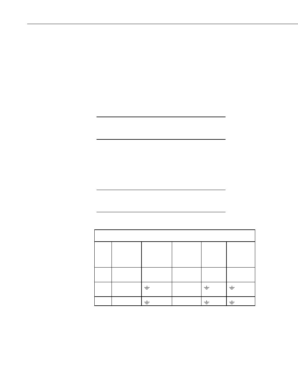
The 52202 is typically wired to a datalogger’s pulse channel (see Table 4-1).
TABLE 4-1. Wiring for Pulse Channel Input
Color
Description
CR800
CR1000
CR3000
CR5000
CR500
CR510,
CR10(X)
21X,
CR7,
CR23X
CR200(X)
Series
Black Signal
Pulse
Channel
Pulse
Channel
Pulse
Channel
P_SW
White Signal
Return
G
Clear Shield
G
4