Wiring, Program examples – Campbell Scientific 4WFB120, 4WFB350, 4WFB1K 4-Wire Full Bridge Terminal Input Module User Manual
Page 7
4WFB120, 4WFB350, 4WFB1K 4 Wire Full Bridge Terminal Input Modules
V
V
V
V
V
r
out
ex
out
ex
=
−
(
/
) (
/
0
)
: 3.1.
ε
=
−
4
1
2
V
G F
V
r
r
(
)
3.2.
The calculations are covered in more detail in section 6.
4. Wiring
Shield
H
L
G
Datalogger
Vx
H
L
or AG
or G
H
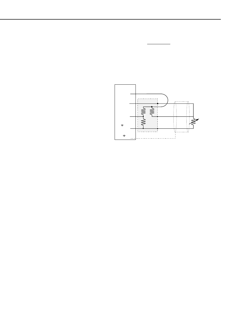
FIGURE 4-1. Wiring for Example Programs
Figure 4-1 illustrates the wiring of the strain gage to the 4WFB module and the
wiring of the module to the datalogger. It is important that the gage be wired
as shown with the wire from H connected at the gage, and that the leads to the
L and G terminals be the same length, diameter, and wire type. With this
configuration, changes in wire resistance due to temperature occur equally in
both arms of the bridge with negligible effect on the output from the bridge.
5. Program Examples
The following examples for the CR10(X), 21X, CR7, and CR9000(X) all have
a subroutine that measures the unstrained "zero" output of the strain gage. The
examples calculate strain using equation 3.2 for a strain gage with a GF=2.
These are just examples. Besides adding additional measurement instructions,
the programs will probably need to have the scan and data storage intervals
altered for actual applications. The instructions in the subroutine will also
need to be modified for the actual gage factor.
This zeroing subroutine is called automatically when the program is first
executed. The user can call the subroutine by setting Flag 1 low using the
datalogger support software or the *6 mode with the keyboard display. The
"zero" reading is then used during normal measurements for the strain
calculations.
3