Measurement concepts – Campbell Scientific 4WFB120, 4WFB350, 4WFB1K 4-Wire Full Bridge Terminal Input Module User Manual
Page 6
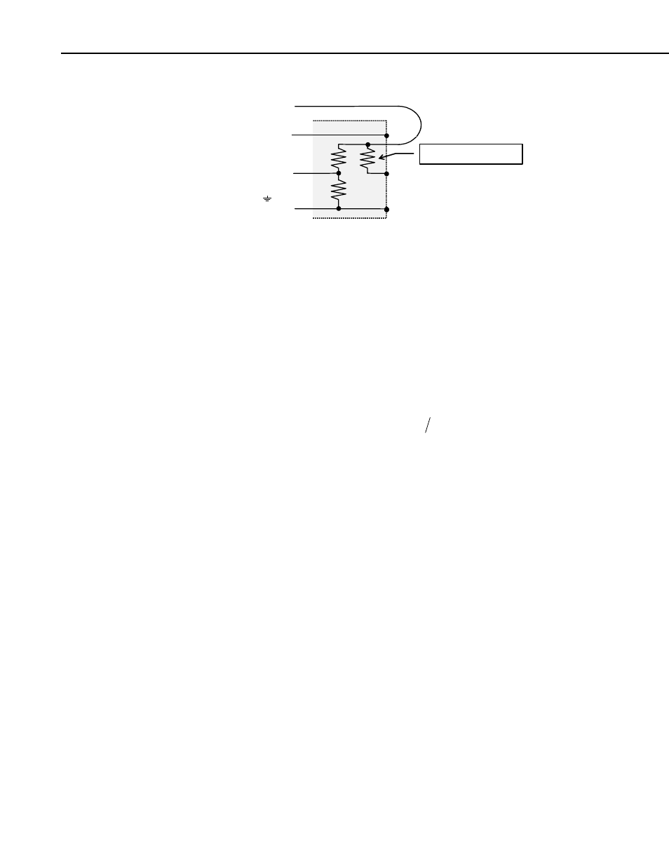
4WFB120, 4WFB350, 4WFB1K 4 Wire Full Bridge Terminal Input Modules
H
L
G
1k
Ω
1k
Ω
Vx
H
L
or AG
H
120
Ω, 350Ω, or 1kΩ
FIGURE 2-1. Schematic
3. Measurement Concepts
Measuring strain is measuring a change in length. Specifically, the unit strain
( )
ε
is the change in length divided by the unstrained length
(
)
.
Strain is typically reported in microstrain
ε
= ∆ l l
/
(
)
µε
; a microstrain is a change in
length by one millionth of the length.
A metal foil strain gage is a resistive element that changes resistance as it is
stretched or compressed. The strain gage is bonded to the object in which
strain is measured. The gage factor,
GF
, is the ratio of the relative change in
resistance for change in strain:
GF
R R
l l
=
∆
∆
/
/
)
. For example, a gage
factor of 2 means that if the length changes by one micrometer per meter of
length
(1
µε
, the resistance will change by two micro-ohms per ohm of
resistance.
Because the actual change in resistance is so small, a full bridge configuration
is used to give the maximum resolution. A "quarter bridge" strain gage is so
named because the strain gage becomes one of the four resistors that make up a
full bridge. The 4WFBxxx module provides the other three resistors (Figure 4-
1). Quarter bridge strain gages are available in nominal unstrained resistances
of 120, 350, and 1000 ohms. The 4WFB model must match the resistance of
the gage (e.g., the 4WFB120 is used with a 120 ohm strain gage).
The resistance of an installed gage will differ from the nominal value. A zero
measurement can be made with the gage installed. This zero measurement can
be incorporated into the datalogger program; subsequent measurements can
report strain relative to the zero.
Strain is calculated in terms of the result of the full bridge measurement. This
result is the measured bridge output voltage divided by the bridge excitation
voltage
V
V
out
ex
/
. (The actual result of the full bridge instruction is the
millivolts output per volt of excitation,
1000
⋅V
V
out
ex
/
) The result of the zero
measurement,
1000
0
⋅V
V
out
ex
/
is stored and used to calculate future strain
measurements. Strain is calculated from the change in the bridge
measurement,
2